
Washing machine with drying device

A drying device and washing machine technology, applied in the field of washing machines, can solve problems such as unsatisfactory drying effect, and achieve the effects of improving drying effect and removing moisture

Inactive Publication Date: 2009-01-14
PANASONIC HOME APPLIANCES R&D CENT HANGZHOU +1
View PDF0 Cites 35 Cited by
  • Summary
  • Abstract
  • Description
  • Claims
  • Application Information

AI Technical Summary

Problems solved by technology

Because the direction of the drying airflow supplied to the inside of the drum is only in a diagonal direction, the drying high-temperature airflow cannot evenly reach the entire space inside the drum, and it is directly discharged from the hot air discharge port above the middle of the tub, making the drying effect unsatisfactory

Method used


Image

  • Washing machine with drying device
  • Washing machine with drying device
  • Washing machine with drying device

Examples


Embodiment 1

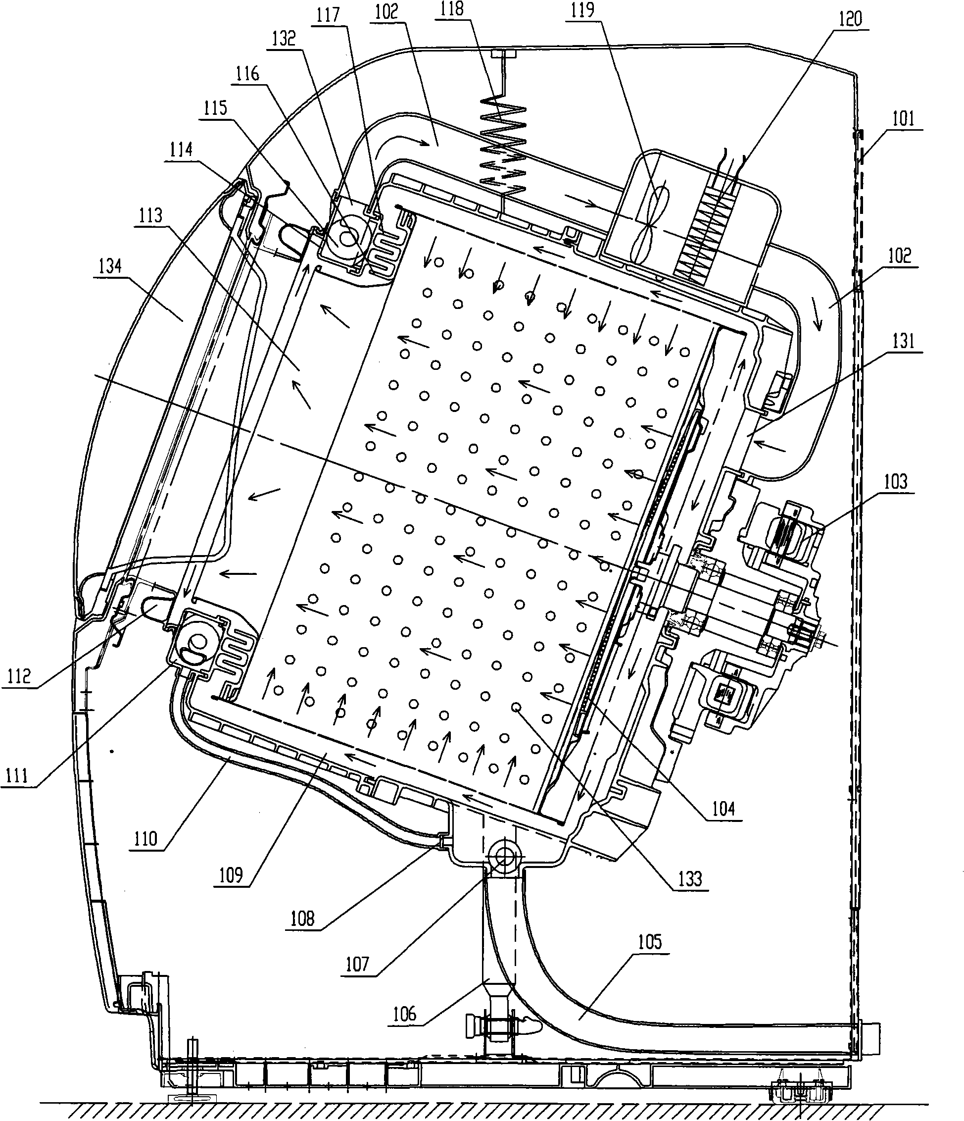
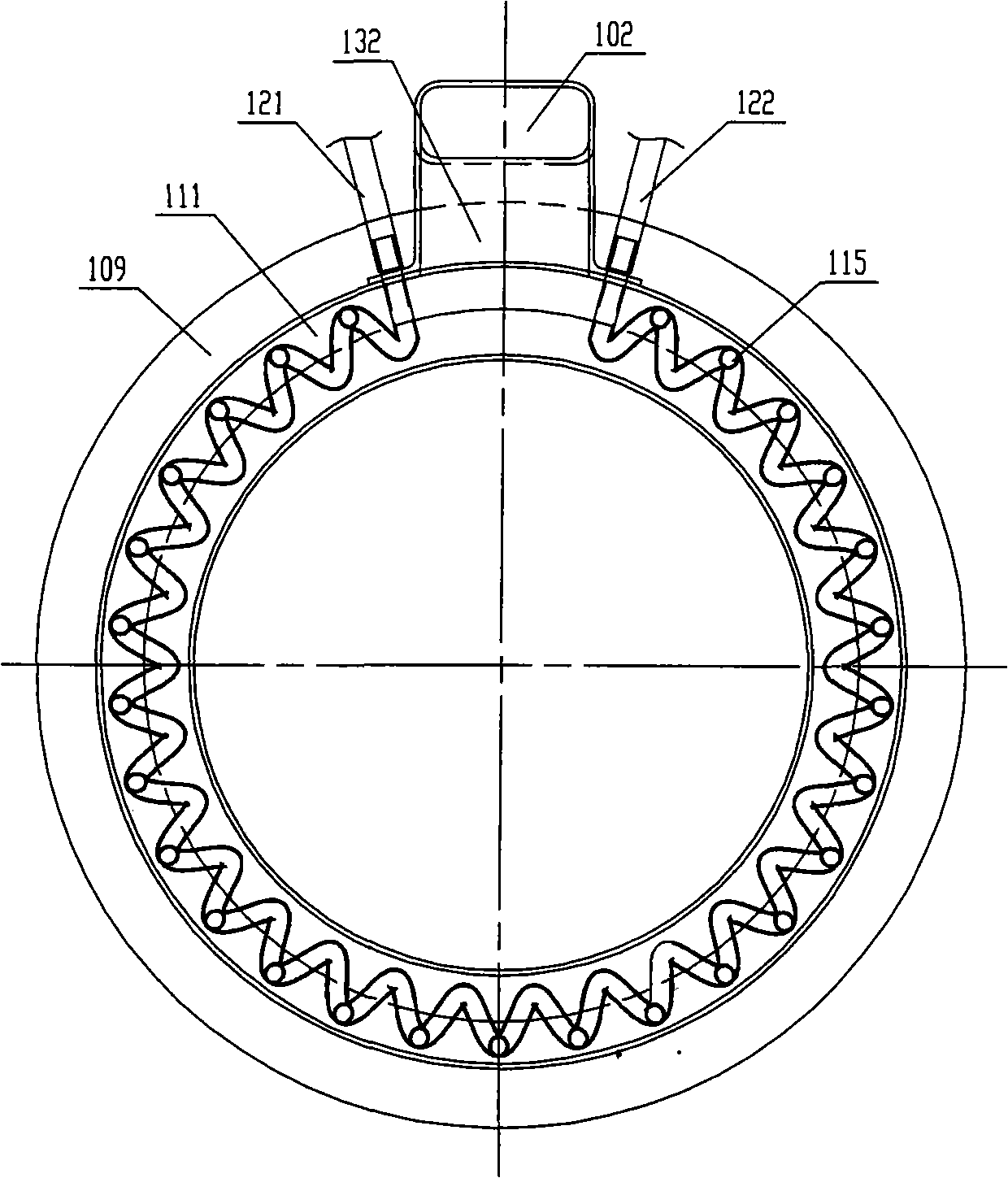
[0031] refer to figure 2 , a washing machine with a drying device, which mainly includes: a washing machine shell 101, a drying pipe 102, a driving motor 103, a drain pipe 105, a shock absorber 106, a drain valve 107, a water bucket 109, a condensate pipe 110, an annular channel 111, Window sealing ring 112, machine door 134, drum 113, windshield 116, suspension spring 118, blower fan 119, heating device 120.

[0032] Said water tub 109 is elastically arranged inside the washing machine shell 101 through suspension springs 118 and shock absorbers 106, and a hot air injection port 131 is provided on its rear end surface, and a window sealing ring 112 and a machine door are provided outside the front opening. 134, the inner surface of its front end is provided with multi-turn ribs 117 protruding inward.

[0033] The drum 113 is disposed inside the tub 109 and driven to rotate by the driving motor 103 . The clothes are stored inside the drum 113, and the clothes are washed, de...

Embodiment 2

[0042] refer to Figure 4 , 5 , The difference between this embodiment and Embodiment 1 mainly lies in the structure of the dehumidification device. The dehumidification device adopts a water-cooling channel 126 with cooling fins 125 arranged in a ring. The cooling fins 125 and the suction holes 114 are distributed on the water-cooling channel at intervals. A port 123 (or 124) of the water-cooling channel 126 is connected to the water injection valve. Another port 124 (or 123) communicates with the drainpipe 105, and the cold water injected from the water-cooling runner 126-port 123 (or 124) exchanges heat with the air-flow in the annular channel 111, and then flows from the other port 124 (or 124) 123) Discharge. The cooling fins 125 on the water-cooling channel 126 are arranged in an arc shape, and are provided with a plurality of small holes to reduce resistance to airflow. The water-cooling channel 126 and the heat sink 125 can be made of metal materials with good therm...


PUM


Abstract

The invention discloses a washing machine with the drying device. The washing machine comprises a washing machine casing as the whole frame of the washing machine; a water holding drum which is elastically arranged inside the washing machine casing and at the rear end of which a hot air filling opening is arranged; a circular channel which is arranged at the front end of the water holding drum opening, on the front end surface of which a plurality of air suction holes are arranged, and on the outer side wall of which an air exhaust opening is arranged; a rolling drum which can be arranged inside the water holding drum in a rotary way, on the bottom end of which air holes are arranged, and on the side wall of which a limber hole is arranged; a hot air isolating device which is arranged between the rolling drum front end and the water hold drum front end, and used to isolate the air; a dehumidifying device which is arranged in the circular channel; a drying pipeline which is arranged outside the water hold drum; a condensation water pipe one end of which is connected with the circular channel and the other end of which is connected with the front part of the water draining valve. The drying device in the washing machine of the invention can cause the drying high temperature air flow to evenly enter into the space inside the rolling drum from the rear end and the side wall, to contact with the wet clothes inside the rolling drum, and the drying effect is greatly enhanced.

Description

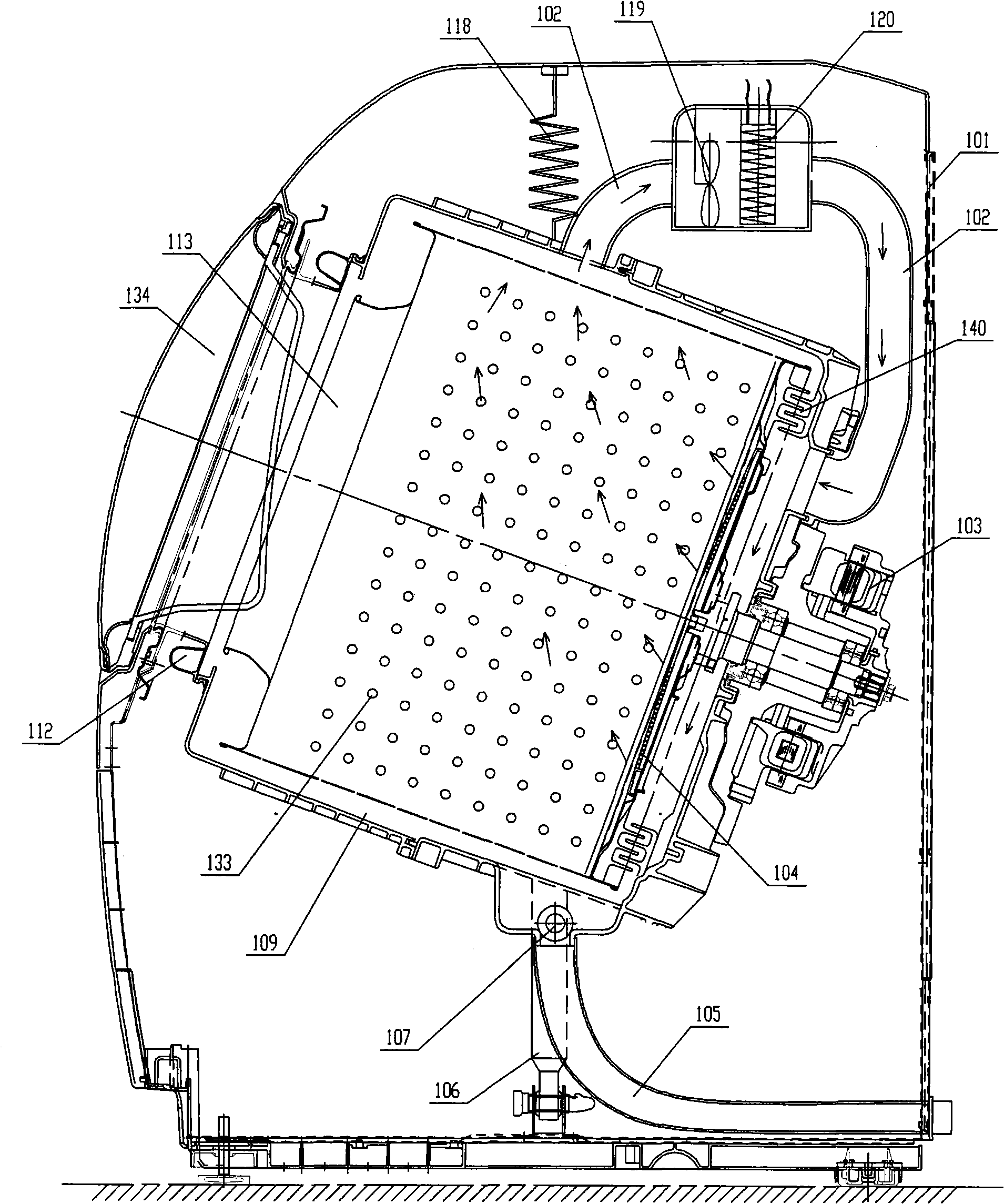
【Technical field】 [0001] The present invention relates to a washing machine for washing fabrics, in particular to a washing machine with a drying device. 【technical background】 [0002] The structure of the washing machine with drying device in the prior art is as figure 1 shown. The water bucket is elastically arranged inside the washing machine shell; the drum is rotatably arranged inside the water bucket, and can accommodate clothes; the air supply pipe is arranged on the upper part of the water bucket, and the blower fan blows air into the air supply pipe, and the heating device will The air is heated into hot air, which reaches the inside of the bucket through the hot air suction port at the back end of the bucket, and then enters the inside of the drum through the vent hole at the bottom of the drum, and contacts the wet clothes inside the drum, evaporating the moisture in the wet clothes and carrying the moisture The humid air passes through the dehumidification dev...

Claims


Application Information

Patent Timeline
Patent Type & Authority Applications(China)
IPC IPC(8): D06F25/00D06F37/20D06F58/10D06F58/20D06F58/22
Inventor 周小皮毛志忠
Owner PANASONIC HOME APPLIANCES R&D CENT HANGZHOU
Learn More