
Low attenuation high light efficiency LED illuminating apparatus and preparation method

A technology of LED lighting and high luminous efficiency, applied in lighting devices, lighting auxiliary devices, components of lighting devices, etc., can solve the problems of no contribution to light, waste, shortened service life, etc., to improve light output efficiency, good consistency, Good size consistency

Inactive Publication Date: 2009-01-07
段永成
View PDF2 Cites 18 Cited by
  • Summary
  • Abstract
  • Description
  • Claims
  • Application Information

AI Technical Summary

Problems solved by technology

[0003] In the actual production process of the above-mentioned known branches, the fluorescent substance is usually prepared into a liquid state, and the fluorescent substance is added to the luminescent material to cover the luminescent material. The disadvantages are: 1. The precipitation of the fluorescent substance is difficult to control uniformly, and it is easy to flow 2. Most of the fluorescent substances are deposited under the side of the luminescent material, which does not contribute to the luminescence and causes serious waste; 3. The fluorescent substances directly interact with the luminescent material. Material contact, the heat emitted by the luminescent material causes a large attenuation of the fluorescent material, thus shortening the service life
How to form a uniform fluorescent substance coating around the light-emitting crystal to manufacture a white light diode with uniform and consistent light emission, and minimize the amount of fluorescent substance used and simplify the curing process of the fluorescent substance film to reduce production costs. Technology does not provide a good solution

Method used


Image

  • Low attenuation high light efficiency LED illuminating apparatus and preparation method

Examples


Embodiment Construction

[0025] Below in conjunction with the preferred embodiment shown in accompanying drawing, be described in further detail:

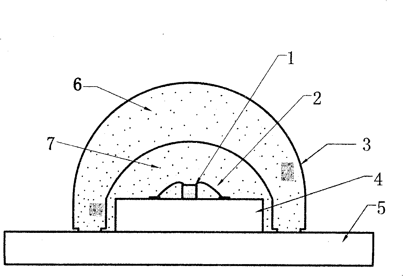
[0026] Such as figure 1 As shown, the aluminum substrate (4) is set on the heat dissipation plate (5), and the LED chip (1) is bound on the aluminum substrate (4); the positive and negative poles of the LED chip (1) are connected to the aluminum substrate (1) with a gold wire (2). The circuit connection on the substrate (4); when forming the transparent cover (3), add the fluorescent substance (6) to one-time molding; fix the transparent cover (3) containing the fluorescent substance (6) on the top of the LED chip, and place it on the aluminum chip when necessary. Silica gel or other transparent filling materials are injected between the substrate (4) and the transparent cover (3).

[0027] The structure of covering the surface of the luminescent material (4) with the liquid fluorescent substance (6) in the production process of the white light emitting d...


PUM


Abstract

The invention discloses a low-attenuation high-lighting effect LED lighting device and a preparation method thereof, and relates to a semiconductor LED lighting device and a preparation method thereof. The lighting device comprises a heat dissipation plate is equipped with an aluminum basal plate, a blue LED chip is fived on the aluminum basal plate and the outer cover of the blue LED chip is a transparent cover. The preparation process is as follows: bonding material is filled on the aluminum basal plate; the luminescent material is fixedly positioned on the bonding material of the aluminum basal plate; the bonding material is baked and dried; a gold wire is used to connect the electrode; the transparent cover material and the fluorescent powder are molded to form the transparent cover; the transparent cover is fixed on the aluminum basal plate; the aluminum basal plate is fixed on a heat-dissipating aluminum plate; the filling material is filled into the space between the aluminum basal plate and the transparent cover; the LED lighting device is baked or dried at ambient temperature; The invention can prolong the service life of the LED lighting device, and promote the luminescence efficiency and the consistency of light and color.

Description

Technical field: [0001] The invention relates to a semiconductor device, especially an LED lighting device and a preparation method. Background technique: [0002] Existing LED lighting devices are usually made of white LEDs that have been packaged and molded. White LEDs usually use blue light, purple light or ultraviolet light to excite RGB fluorescent materials to obtain white light. Chinese patent application 200310120736 discloses a "surface-mounted white light-emitting diode", Chinese patent ZL 021003459 discloses "a high-brightness nitride light-emitting diode and its preparation method", and Chinese patent application 01141509 discloses "a white light-emitting Diode Fabrication Method". [0003] In the actual production process of the above-mentioned known branches, the fluorescent substance is usually prepared into a liquid state, and the fluorescent substance is added to the luminescent material to cover the luminescent material. The disadvantages are: 1. The preci...

Claims


Application Information

Patent Timeline
Patent Type & Authority Applications(China)
IPC IPC(8): F21S2/00F21V29/00F21V21/00F21V3/04F21V9/08H01L33/00F21Y101/02H01L33/48H01L33/52H01L33/58H01L33/64
CPCH01L33/52H01L33/641H01L33/483H01L33/58H01L2224/45144H01L2224/48091H01L2924/181
Inventor 段永成
Owner 段永成
Learn More