Torque detecting apparatus and electric power steering apparatus
A technology of torque detection and detector, which is applied in the direction of electric steering mechanism, measuring device, torque measurement, etc., can solve the problems of increasing the number of components, increasing the cost of components, and not being able to guarantee the mechanical adhesion of the circuit board, so as to reduce the The effect of reducing the number of parts and the cost of parts
- Summary
- Abstract
- Description
- Claims
- Application Information
AI Technical Summary
Problems solved by technology
Method used
Image


Examples
Embodiment approach 1
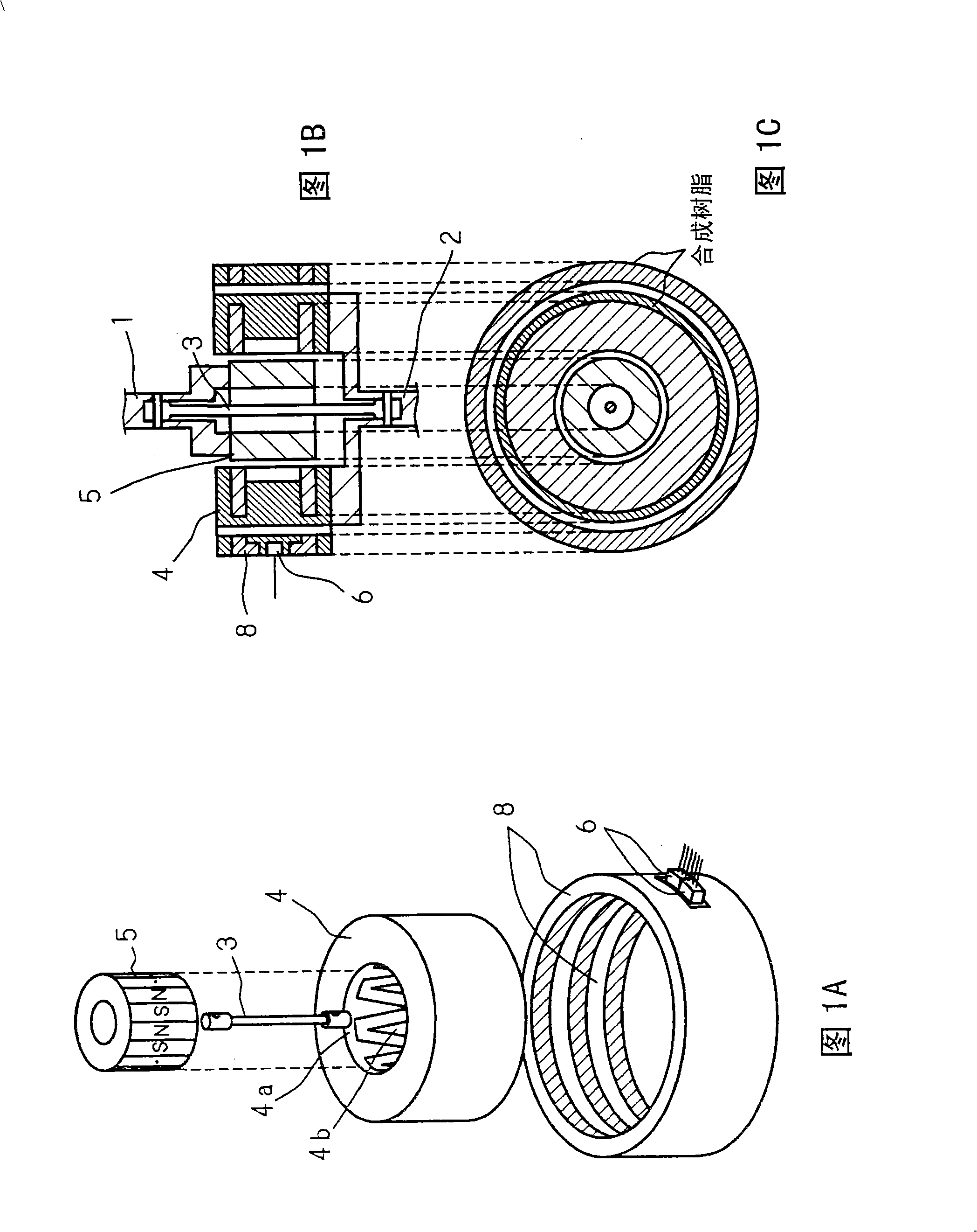
[0047] 3A to 3C are explanatory views showing the configuration of Embodiment 1 of the torque detection device of the present invention. Fig. 3A is an exploded perspective view, Fig. 3B is a longitudinal sectional view, and Fig. 3C is a cross-sectional body of the A-A' plane of Fig. 3B. In this torque detection device, an input shaft 1 (first shaft) and an output shaft (second shaft) are coaxially connected via a small-diameter torsion bar 3 (connecting shaft). The input shaft 1 and the output shaft 2 are respectively connected to the torsion bar 3 via pins 9 .
[0048] A cylindrical permanent magnet 5 (24 poles) is coaxially fixed to the input shaft 1, and the permanent magnet 5 magnetizes 24 poles (12 poles each for N and S poles) at equal intervals in the circumferential direction. On the output shaft 2, through the shaft sleeve 25 ( Figure 5 ), coaxially press into the fixed cylindrical yoke 4, and the yoke 4 surrounds the permanent magnet 5 with an appropriate gap in t...
Embodiment approach 2
[0066] 7A to 7C are explanatory views showing the configuration of Embodiment 2 of the torque detection device of the present invention. Fig. 7A is an exploded perspective view, Fig. 7B is a longitudinal sectional view, and Fig. 7C is a cross-sectional body of the A-A' plane of Fig. 7B. In this torque detection device, an input shaft 1 (first shaft) and an output shaft (second shaft) are coaxially connected via a small-diameter torsion bar 3 (connecting shaft). The input shaft 1 and the output shaft 2 are respectively connected to the torsion bar 3 via pins 9 .
[0067] On the input shaft 1, a cylindrical permanent magnet 5 (24 poles) is fixed coaxially, and the permanent magnet 5 magnetizes 24 poles (12 poles each for N and S poles) at equal intervals in the circumferential direction. A cylindrical yoke 4 is press-fitted coaxially onto the output shaft 2 and fixed, and the yoke 4 surrounds the permanent magnet 5 with an appropriate gap in the radial direction. Yoke 4, such ...
Embodiment approach 3
[0074] 10A to 10C are explanatory diagrams schematically showing the configuration of Embodiment 3 of the torque detection device of the present invention. Fig. 10A is an exploded perspective view, Fig. 10B is a longitudinal sectional view, and Fig. 10C is a cross-sectional body on the A-A' plane of Fig. 10B. In this torque detection device, an input shaft 1 (first shaft) and an output shaft (second shaft) are coaxially connected via a small-diameter torsion bar 3 (connecting shaft). The input shaft 1 and the output shaft 2 are respectively connected to the torsion bar 3 via positioning pins 9 .
[0075] A cylindrical permanent magnet 5 (24 poles) is coaxially fixed to the input shaft 1, and the permanent magnet 5 magnetizes 24 poles (12 poles each for N and S poles) at equal intervals in the circumferential direction.
[0076] A cylindrical yoke 4 is press-fitted coaxially onto the output shaft 2 and fixed, and the yoke 4 surrounds the permanent magnet 5 with an appropriate ...
PUM
 Abstract
Description
Claims
Application Information
 - R&D
- Intellectual Property
- Life Sciences
- Materials
- Tech Scout
- Unparalleled Data Quality
- Higher Quality Content
- 60% Fewer Hallucinations
Browse by: Latest US Patents, China's latest patents, Technical Efficacy Thesaurus, Application Domain, Technology Topic, Popular Technical Reports.
© 2025 PatSnap. All rights reserved.Legal|Privacy policy|Modern Slavery Act Transparency Statement|Sitemap|About US| Contact US: help@patsnap.com