Method for forming stress layer of complementary metal oxide semiconductor device

A stress layer and device technology, applied in semiconductor/solid-state device manufacturing, electrical components, circuits, etc., can solve problems such as bumps, achieve the effects of reducing use, reducing manufacturing costs, and improving connection accuracy

Active Publication Date: 2008-12-24
SEMICON MFG INT (SHANGHAI) CORP +1
View PDF1 Cites 19 Cited by
  • Summary
  • Abstract
  • Description
  • Claims
  • Application Information

AI Technical Summary

Problems solved by technology

When the stress layer 18 is deposited, the stress layer covers the previously formed stress layer 16, so after removing the photoresist pattern 50', it is easy to have a raised phenomenon at the junction of the stress layer 156 and 18

Method used


Image

  • Method for forming stress layer of complementary metal oxide semiconductor device
  • Method for forming stress layer of complementary metal oxide semiconductor device
  • Method for forming stress layer of complementary metal oxide semiconductor device

Examples


Embodiment Construction

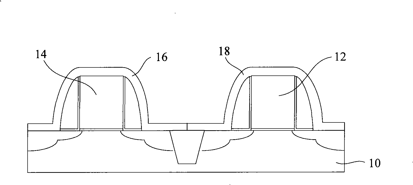
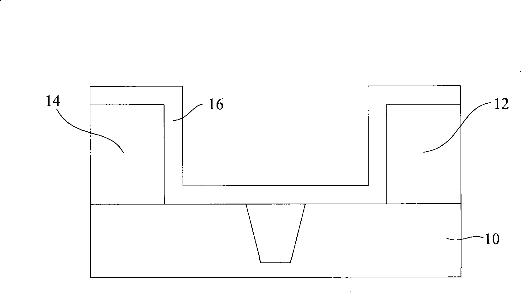
[0036] In order to make the above objects, features and advantages of the present invention more comprehensible, specific implementations of the present invention will be described in detail below in conjunction with the accompanying drawings.

[0037] The stress layer forming method provided by the invention relates to PMOS transistors and NMOS transistors in CMOS devices. In order to make the above objects, features and advantages of the present invention more comprehensible, preferred embodiments of the present invention will be described in detail below in conjunction with the accompanying drawings. In the following description, numerous specific details are set forth in order to provide a thorough understanding of the present invention. However, the present invention can be implemented in many ways other than those described here, and those skilled in the art can make similar extensions without departing from the connotation of the present invention. Accordingly, the inv...


PUM


Abstract

The invention discloses a formation method of a stress layer of a CMOS device, which comprises the following steps; a tensile stress layer is formed on the surfaces of an NMOS transistor and a PMOS transistor; a positive photoresist is coated on the surface of the tensile stress layer; the positive photoresist is patterned by utilizing a mask blank so as to form a photoresist mask pattern exposing on the tensile stress layer on the surface of the PMOS transistor; the tensile stress layer on the surface of the PMOS transistor is etched and the photoresist mask pattern is removed; a compressive stress layer is sedimentated on the tensile stress layer and the surface of the PMOS transistor; a negative photoresist is coated on the surface of the compressive stress layer; the negative photoresist is patterned by utilizing the mask blank so as to form a photoresist mask pattern exposing on the compressive stress layer on the surface of the NMOS transistor; the compressive stress layer on the surface of the NMOS transistor is etched and the photoresist mask pattern is removed. The formation method of the invention can form the photoresist mask patterns of the tensile stress layer and the compressive stress layer just by using the same mask blank, thus not only reducing the manufacturing cost but also promoting the precision of connection of the tensile stress layer with the compressive stress layer.

Description

technical field [0001] The invention relates to the technical field of semiconductor manufacturing, in particular to a method for forming a stress layer of a complementary metal oxide semiconductor device (CMOS). Background technique [0002] In semiconductor manufacturing technology, it is known that the formation of a stress layer on a doped region can generate mechanical stress on the underlying layer or substrate containing doped impurities, through which the speed of the associated semiconductor device can be increased. Such stress can increase the mobility of dopant impurities. The increased mobility of dopants or charge carriers enables semiconductor devices to operate at higher speeds. In the past ten years, the operation speed, performance, circuit element density and cost of each functional element of integrated circuits have been continuously improved by reducing the size of metal oxide semiconductor field effect transistors (MOSFETs). The reduction method mainl...

Claims


Application Information

Patent Timeline
Patent Type & Authority Applications(China)
IPC IPC(8): H01L21/8238
Inventor 吴汉明
Owner SEMICON MFG INT (SHANGHAI) CORP
Why Eureka
Try Eureka