
Dry coal powder airflow bed gasification furnace

A technology of entrained bed and dry coal powder, which is applied in the direction of granular/powdered fuel gasification, etc., can solve the problems of gasification reaction area deviation, increase the average temperature level of the upper furnace body, etc., achieve complete gasification reaction and improve gasification Efficiency, increased contact and reaction time effects

Inactive Publication Date: 2008-12-24
UNIV OF SCI & TECH OF CHINA
View PDF1 Cites 19 Cited by
  • Summary
  • Abstract
  • Description
  • Claims
  • Application Information

AI Technical Summary

Problems solved by technology

However, due to the feeding method of single coal powder radial nozzle, it is easy to cause the coal powder to directly hit the inner tank of the furnace, and the single gasification agent feeding method along the circumference of the tangential nozzle is easy to make the gasification reaction area deviate from the center of the gasifier; , the water vapor injected by the nozzles in the lower section quickly reduces the temperature of the syngas, and to maintain the liquid slagging of coal gasification with high ash melting point, the average temperature level of the upper section of the furnace body must be raised, which will put more stringent requirements on the furnace liner material requirements

Method used


Image

  • Dry coal powder airflow bed gasification furnace
  • Dry coal powder airflow bed gasification furnace
  • Dry coal powder airflow bed gasification furnace

Examples


Embodiment Construction

[0023] see figure 1 , the outer wall 9 of the gasification furnace is an upright cylinder, and the internal structure is composed of the main gasification chamber 13 in the upper section and the quenching chamber 14 in the lower section.

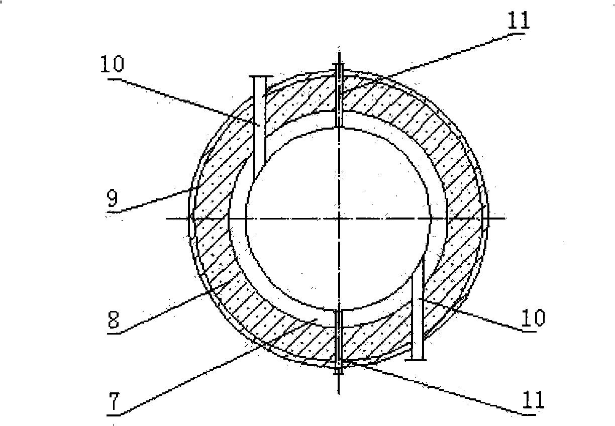
[0024] The main gasification chamber 13 in the upper section is a water-cooled wall structure, which is surrounded by a coil-type water-cooled wall 7 , a refractory insulation layer 8 and an outer wall 9 from the inside to the outside. On the upper part of the main gasification chamber 13, there are two first-stage pulverized coal nozzles 11 of the center-to-spray type and two two first-stage gasification agent nozzles 10 parallel to the first-stage pulverized coal nozzles 11 and offset to each other by a certain distance, see figure 2 , the offset is the inner diameter of the main gasification chamber 13 Arrange two secondary pulverized coal nozzles 12 and two secondary gasifying agent nozzles 16 in the middle of the main gasification ch...


PUM


Abstract

A dry coal dust entrained flow gasification furnace comprises the structure that: an outer wall is a vertical cylinder and the inner structure consists of an upper main gasification chamber and a lower chilling chamber; the main gasification chamber is horizontally provided with a coal dust-gasification agent nozzle, while the chilling chamber is provided with a chilling water atomization nozzle, a slag notch and a synthetic gas outlet. The dry coal dust entrained flow gasification furnace is characterized in that: the upper part of the main gasification chamber is provided with two first-stage coal dust nozzles of central opposite spray type and two first-stage gasification agent nozzles parallel to the first-stage coal dust nozzles and deflecting a certain distance opposite to each other; meanwhile, the middle part of the main gasification chamber is provided with two second-stage coal dust nozzles and two second-stage gasification agent nozzles in an identical mode; moreover, the first-stage coal dust nozzles are perpendicular to the central lines of the second-stage coal dust nozzles, and the rotation directions of gasification agents sprayed out by the first-stage gasification agent nozzles and the second-stage gasification agent nozzles are identical. The dry coal dust entrained flow gasification furnace realizes spatial gasification reaction and more even in-furnace temperature field, and in-furnace average temperature is 50 DEG C higher than ash fusion point; therefore, clinker can be smoothly discharged in liquid state, and safe and efficient gasification of coal dust is realized.

Description

Technical field: [0001] The invention relates to a gasification device, in particular to a dry coal pulverized entrained bed gasification furnace. Background technique: [0002] Clean coal technology has become a major key technology for my country's coal chemical industry, industrial gas and power industry technology upgrades, and coal gasification technology is one of the important directions of clean coal technology, and is the most important in the chemical system with coal-based energy. Core Technology. So far, there are dozens of industrialized coal gasification processes in the world, which can be classified into three categories: fixed bed gasification process represented by Lurgi; gasification process represented by HTW (High Temperature Winkler) and ash fusion Fluidized bed gasification process; entrained bed gasification process represented by Texaco, Shell, GSP. Coal-to-syngas (or H 2 ) gasification technology is generally recognized as the entrained bed gasifi...

Claims


Application Information

Patent Timeline
IPC IPC(8): C10J3/56
Inventor 唐志国唐超君邢献军林其钊
Owner UNIV OF SCI & TECH OF CHINA
Learn More