Semiconductor device mixed with magnetic substance powder and its manufacturing method

A manufacturing method and semiconductor technology, applied in the fields of semiconductor/solid-state device manufacturing, semiconductor devices, semiconductor/solid-state device components, etc., can solve the problems of deterioration of characteristics of thin-film inductance components, inability to suppress interference electromagnetic radiation noise, etc., to reduce eddy current loss Effect

Inactive Publication Date: 2012-02-22
AOI ELECTRONICS CO LTD
View PDF1 Cites 0 Cited by
  • Summary
  • Abstract
  • Description
  • Claims
  • Application Information

AI Technical Summary

Problems solved by technology

[0003] However, in JP-A-2004-342876 ( Image 6 ), the upper surface side of the semiconductor substrate can be protected from contamination and damage from the external atmosphere by means of a sealing film formed of epoxy resin, etc., but there is a problem that it cannot be suppressed from the upper surface side of the semiconductor substrate to Disturbing electromagnetic radiation noise from the outside, or conversely from the outside to the upper surface side of the semiconductor substrate
[0005] However, in Japanese Patent No. 3540729, since the spiral-shaped thin-film inductor element is provided on the upper surface of the protective film, there is a problem that, under the action of the eddy current generated in the semiconductor substrate, the thin-film inductor element Eddy current loss, which degrades the characteristics of thin film inductors (Q value decreases)

Method used


Image

  • Semiconductor device mixed with magnetic substance powder and its manufacturing method
  • Semiconductor device mixed with magnetic substance powder and its manufacturing method
  • Semiconductor device mixed with magnetic substance powder and its manufacturing method

Examples


no. 1 Embodiment approach

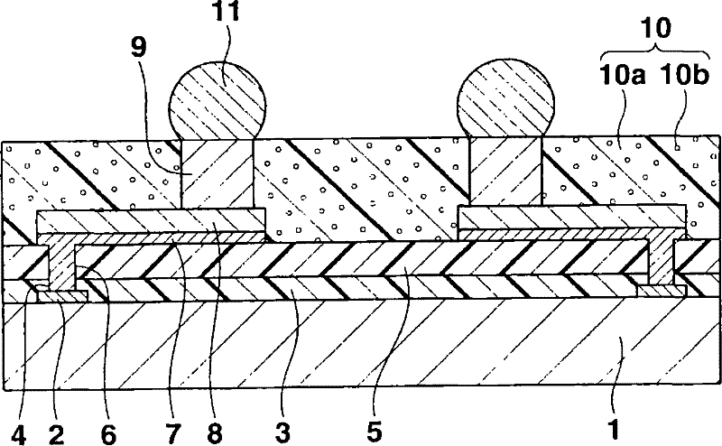
[0035] figure 1 A cross-sectional view of the semiconductor device according to the first embodiment of the present invention is shown. This semiconductor device is generally called a CSP, and includes a silicon substrate (semiconductor substrate) 1 . An integrated circuit (not shown) with a predetermined function is provided on the upper surface of the silicon substrate 1, and a plurality of connection pads 2 made of aluminum-based metal or the like are provided in connection with the integrated circuit on the peripheral portion of the upper surface.

[0036] An insulating film 3 made of silicon oxide or the like is provided on the upper surface of the silicon substrate 1 except for the central portion of the connecting pad 2 exposed through the opening 4 provided in the insulating film 3 . A protective film 5 formed of a thermosetting resin such as polyimide resin or epoxy resin is provided on the upper surface of the insulating film 3 . On a portion corresponding to the ...

no. 2 Embodiment approach

[0048] Figure 10 A cross-sectional view of a semiconductor device as a second embodiment of the present invention is shown. The semiconductor device and figure 1 The semiconductor device shown in is different in that the protective film (insulating film) 5 is formed of a material in which a soft magnetic powder 5b is mixed into a thermosetting resin 5a formed of polyimide resin, epoxy resin, or the like. .

[0049] In this semiconductor device, under the action of the soft magnetic powder 10b, 5b in the sealing film 10 and the protective film 5, it figure 1 The case of the semiconductor device shown in , further suppresses disturbing electromagnetic radiation noise from the upper surface side (integrated circuit) of the silicon substrate 1 to the outside, or vice versa from the outside to the upper surface side (integrated circuit) of the silicon substrate 1. In addition, when forming the protective film 5, the thermosetting resin 5a mixed with the soft magnetic powder 5...

no. 3 Embodiment approach

[0051] Figure 11 (A) is a perspective plan view of a main part of a semiconductor device as a third embodiment of the present invention, Figure 11 (B) is a cross-sectional view along its B-B line. This semiconductor device is generally called a CSP, and includes a planar square silicon substrate (semiconductor substrate) 1 . An integrated circuit (not shown) with a predetermined function is provided on the upper surface of the silicon substrate 1, and a plurality of connection pads 2a, 2b, 2c formed of aluminum-based metal or the like are provided in connection with the integrated circuit on the peripheral portion of the upper surface. In this case, the connection pads indicated by symbols 2b and 2c are connected to both ends of the spiral thin film inductor element 13 described later, and Figure 11 (A) are arranged adjacent to each other.

[0052] An insulating film 3 formed of silicon oxide or the like is provided on the upper surface of the silicon substrate 1 except ...


PUM


Abstract

The invention relates to a semiconductor device mixed with magnetic powder and a manufacturing method thereof. According to the invention, because a material mixed with the magnetic powder in the resin forms a sealing membrane, interfering electromagnetic radiation noise can be restrained from an integrated circuit on the upper surface of a semiconductor substrate to the exterior or inversely from the exterior to an integrated circuit on the upper surface of a semiconductor substrate. In addition, in a semiconductor device comprising a spiral membrane inductive component named as CSP, a magnetic membrane formed by a material mixed with the magnetic powder in the resin is arranged between the semiconductor substrate and the membrane inductive component, thereby reducing eddy current loss of the membrane inductive component caused by eddy current generated in the semiconductor substrate.

Description

technical field [0001] The present invention relates to a semiconductor device mixed with magnetic substance powder and its manufacturing method. Background technique [0002] In Japanese Patent Application Publication No. 2004-342876 ( Image 6 ) discloses a semiconductor device called CSP (chipsize package), which is provided with a plurality of wirings on a semiconductor substrate, and a columnar electrode is provided on the upper surface of the connection pad part of the wiring, including A sealing film made of epoxy resin or the like is provided on the wired semiconductor substrate so that its upper surface is flush with the upper surface of the columnar electrodes, and solder balls are provided on the upper surfaces of the columnar electrodes. [0003] However, in JP-A-2004-342876 ( Image 6 ), the upper surface side of the semiconductor substrate can be protected from contamination and damage from the external atmosphere by means of a sealing film formed of epoxy resi...

Claims


Application Information

Patent Timeline
Patent Type & Authority Patents(China)
IPC IPC(8): H01L23/552H01L21/822H01L21/56H01L23/522H01L27/04H01L23/31H01L21/00
CPCH01L2924/01072H01L2924/0103H01L23/3114H01L2924/01046H01L24/94H01L24/03H01L23/525H01L24/13H01L2924/14H01L24/05H01L2924/01005H01L2924/01029H01L2924/01078H01L2924/01027H01L23/552H01L2924/01073H01L2224/94H01L23/645H01L2224/023H01L2224/0401H01L2224/13H01L2224/03H01L2924/00H01L2924/0001
Inventor 青木由隆
Owner AOI ELECTRONICS CO LTD
Why Eureka
Try Eureka