High-efficiency air source heat pump suitable for cold surroundings

A high-efficiency air-source heat pump technology, applied in the field of heat pump systems and high-efficiency air-source heat pumps, can solve problems such as slow heating speed, liquid shock, and evaporation of frost-prone refrigerants, and achieve high heating efficiency and heating capacity Effect

Inactive Publication Date: 2008-12-10
惠州市思想科技有限公司
View PDF0 Cites 6 Cited by
  • Summary
  • Abstract
  • Description
  • Claims
  • Application Information

AI Technical Summary

Problems solved by technology

When the ambient air temperature of the air-cooled evaporator is low, it is easy to frost and cause insufficient refrigerant evaporation in the system, low return air pressure, high exhaust temperature, liquid shock and other adverse phenomena. At this time, the heating efficiency of the heat pump Rapid decline, unstable system operation, and slow heating speed. For this reason, people usually design defrosting functions for air source heat pumps. Under the existing conventional technologies, the most widely used methods are reversing defrosting and electric heating defrosting. frost, etc., but the air source heat pumps of these technologies are either forced to stop and start frequently during defrosting, or consume a lot of energy, resulting in very poor heating capacity of the heat pump at this time, or even not saving energy. Therefore, Its use effect and actual service life when working in cold environmental conditions are not fully satisfactory, which also greatly limits the popularization and application of this energy-saving and environment-friendly heating equipment

Method used


Image

  • High-efficiency air source heat pump suitable for cold surroundings
  • High-efficiency air source heat pump suitable for cold surroundings
  • High-efficiency air source heat pump suitable for cold surroundings

Examples


Embodiment 1

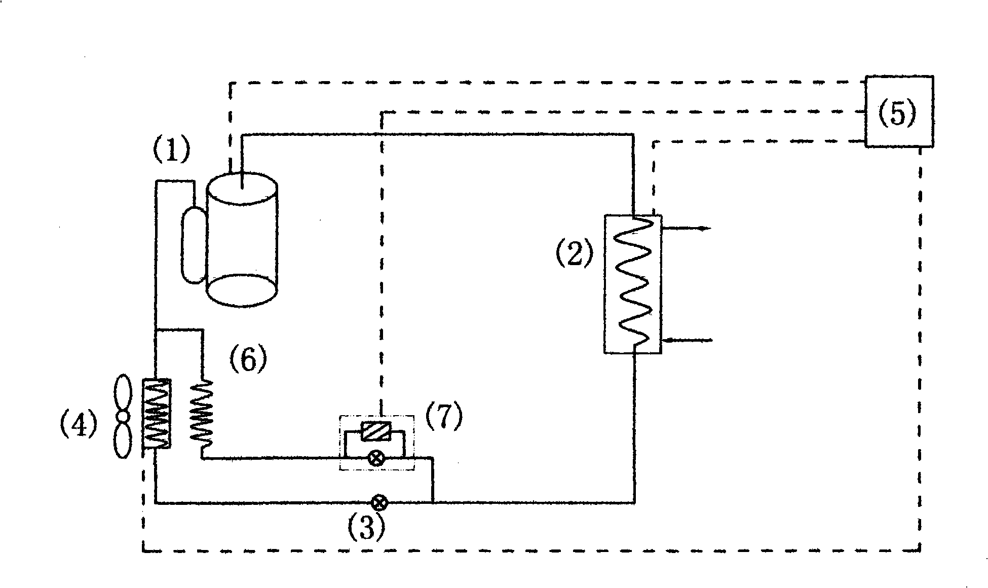
[0011] Embodiment 1: A high-efficiency air source heat pump suitable for cold environments, mainly composed of a compressor (1), an indoor heat exchanger (2), a throttling device (3) and an outdoor air-cooled heat exchanger (4), A proper amount of copper pipes and other fittings are sequentially connected to form a refrigerant closed circulation passage system. The system is controlled by an electric control device (5). In particular, a natural energy heat exchanger (6) is connected to the above system. The natural energy heat exchanger (6) is arranged on the air inlet side of the outdoor air-cooled heat exchanger (4), and the outlet of the natural energy heat exchanger (6) exchanges heat with the outdoor air-cooled heat exchanger through an appropriate amount of copper pipes and other accessories. connected to the outlet of the device (4), the inlet of the natural energy heat exchanger (6) is connected to the outlet of a throttling assembly (7) through an appropriate amount of...

Embodiment 2

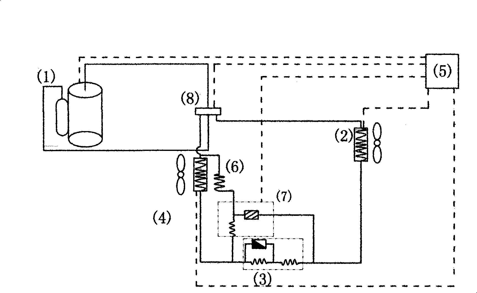
[0015]Embodiment 2: A high-efficiency air source heat pump suitable for cold environments, mainly including a compressor (1), a four-way reversing valve (8), an indoor heat exchanger (2), a throttling device (3), and an outdoor fan The cold heat exchanger (4) is composed of an appropriate amount of copper pipes and other fittings to form a refrigerant closed cycle passage system. The system is controlled by the electric control device (5). In particular, there is a A natural energy heat exchanger (6), a part of the natural energy heat exchanger (6) is arranged on the air inlet side of a part of the outdoor air-cooled heat exchanger (4), and the outlet of the natural energy heat exchanger (6) The outlet of the outdoor air-cooled heat exchanger (4) is connected through an appropriate amount of copper pipes and other accessories, and the inlet of the natural energy heat exchanger (6) is connected with the outlet of a throttling assembly (7) through an appropriate amount of copper ...

Embodiment 3

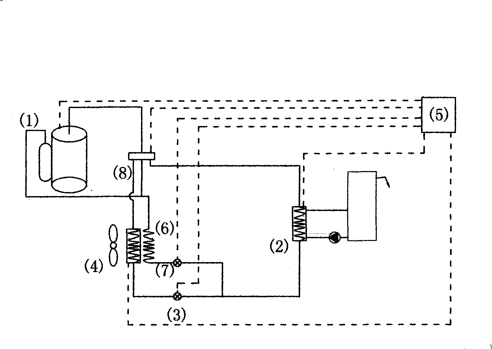
[0020] Embodiment 3: A high-efficiency air source heat pump suitable for cold environments, mainly including a compressor (1), a four-way reversing valve (8), an indoor heat exchanger (2), a throttling device (3), and an outdoor fan The cold heat exchanger (4) is composed of an appropriate amount of copper pipes and other fittings to form a refrigerant closed cycle passage system. The system is controlled by the electric control device (5). In particular, there is a Natural energy heat exchanger (6), the natural energy heat exchanger (6) is arranged on the air inlet side of the outdoor air-cooled heat exchanger (4), and the outlet of the natural energy heat exchanger (6) passes through an appropriate amount of copper pipe and other accessories are connected with the low-pressure gas outlet of the four-way reversing valve (8), and the inlet of the natural energy heat exchanger (6) is connected with the outlet of a throttling assembly (7) through an appropriate amount of copper p...


PUM


Abstract

The invention relates to a high efficiency air source heat pump, belongs to the heat pump applied technology field, mainly comprising a compressor (1) and an indoor heat exchanger (2). A throttling device (3) and an outdoor air cooling heat exchanger (4) form a refrigerant closed cycle system which is controlled by an electric control device (5). The high efficiency air source heat pump is characterized in that the system is also connected with a natural energy heat exchanger (6). At least one part of the natural energy heat exchanger (6) is arranged on the air inlet side of the outdoor air cooling heat exchanger (4). The outlet of the natural energy heat exchanger (6) is connected with the air return channel of the system. The inlet of the natural energy heat exchanger is connected with the outlet of a throttling component (7). The inlet of the throttling component (7) is connected with the throttling device (3). The throttling component (7) is an electronic expansion valve or a non-electronic control restrictor part and an electronic control valve with the inlets are connected with each other. The high efficiency air source heat pump can produce heat with high efficiency and quick speed, especially under the low temperature and cold environment conditions. The flexibility and defrosting functions can make the system have stable operation property and long service lift. The high efficiency air source heat pump is suitable for being expanded and applied in a wide scope.

Description

Technical field [0001] The invention relates to a heat pump system, in particular to a high-efficiency air source heat pump suitable for cold environments, and belongs to the technical field of heat pump applications. Background technique [0002] Because of its heating energy efficiency ratio is always greater than 1, heat pumps have obvious energy-saving advantages, and have been vigorously promoted and applied in modern energy-scarce society. Among them, the application of air source heat pumps has attracted more and more attention. The working principle of the air source heat pump in the prior art is: the refrigerant is compressed by the compressor into a high-temperature and high-pressure gaseous refrigerant, enters the condenser, releases heating heat and condenses into a medium-temperature and medium-pressure liquid refrigerant, and then throttling The device is decompressed into a low-temperature and low-pressure liquid refrigerant, which flows into the air-cooled ev...

Claims


Application Information

Patent Timeline
IPC IPC(8): F25B30/02
Inventor 秦恩溢
Owner 惠州市思想科技有限公司
Why Eureka
Try Eureka