
White light LED and base thereof

A light-emitting diode and white light technology, which is applied in semiconductor/solid-state device components, semiconductor devices, electrical components, etc., can solve the problems of white light-emitting diodes being difficult to popularize, inconvenient, and unsuitable

Inactive Publication Date: 2008-11-12
LITE ON TECH CORP
View PDF4 Cites 0 Cited by
  • Summary
  • Abstract
  • Description
  • Claims
  • Application Information

AI Technical Summary

Problems solved by technology

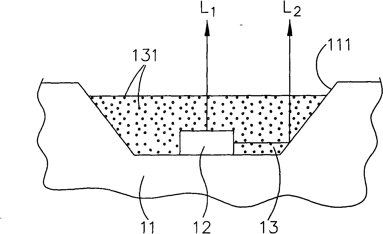
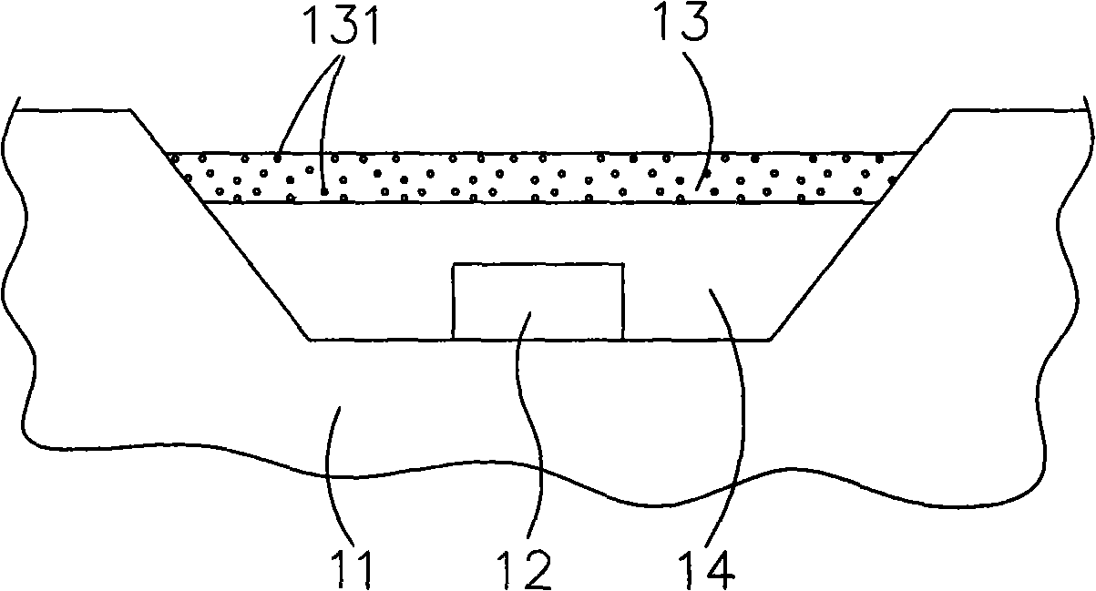
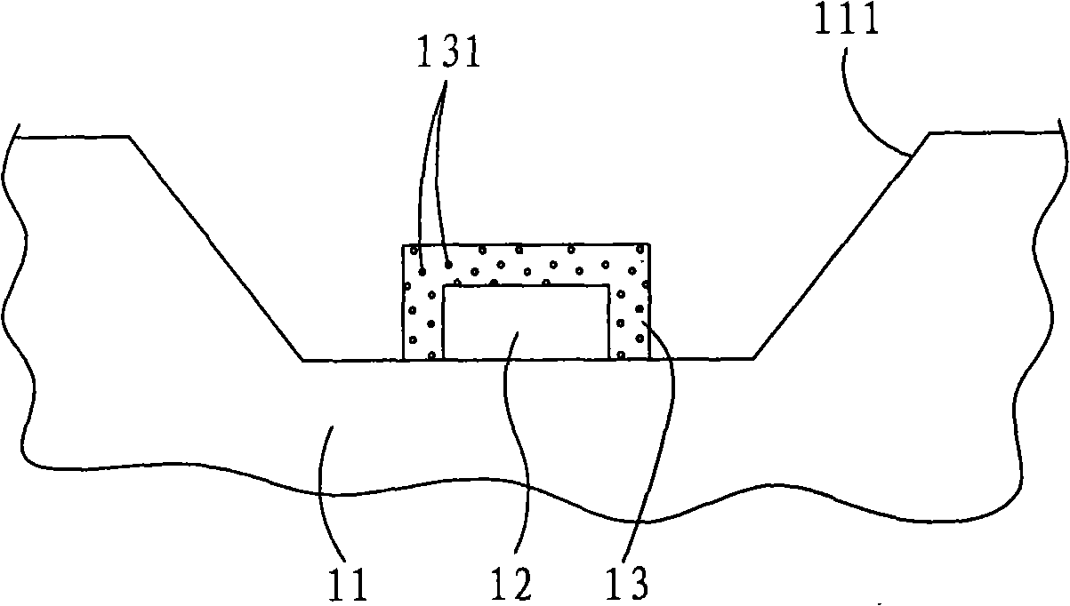
[0007] However, this method can only be used if Figure 4 ( Figure 4 It is another kind of flip-chip bonding (flip chip bonding) type light-emitting chip 12 shown in the structural schematic diagram of an existing white light-emitting diode in the past, which cannot be applied to a light-emitting chip that needs to be bonded by wire bonding (wire bonding), so that limited in application
Moreover, the additional production cost of electrophoresis and other processes also makes it difficult to popularize this kind of white light emitting diode.
[0008] It can be seen that the above-mentioned existing white light emitting diode and its base obviously still have inconvenience and defects in structure and use, and need to be further improved urgently.
In order to solve the above-mentioned problems, the relevant manufacturers have tried their best to find a solution, but no suitable design has been developed for a long time, and the general products do not have a suitable structure to solve the above-mentioned problems. This is obviously related. The problem that the industry is eager to solve

Method used


Image

  • White light LED and base thereof
  • White light LED and base thereof
  • White light LED and base thereof

Examples


Embodiment Construction

[0036] In order to further explain the technical means and effects of the present invention to achieve the intended purpose of the invention, the specific implementation, structure and characteristics of the white light-emitting diode and its base proposed by the present invention will be described below in conjunction with the accompanying drawings and preferred embodiments. And its effect, detailed description is as follows.

[0037] see Figure 5 Shown is a schematic structural view of a preferred embodiment of the white light emitting diode of the present invention. A preferred embodiment of the white light emitting diode of the present invention includes a base 21 , a light emitting chip 22 , and a fluorescent layer 23 .

[0038] Above-mentioned pedestal 21, its upper surface is sunken downwards to form a concave part 210, and concave part 210 has a bottom surface 211, and a side wall surface 212 that uprightly surrounds the periphery of bottom surface 211, and bottom su...


PUM


Abstract

The invention relates to a white light-emitting diode and a substrate thereof. The white light-emitting diode consists of a substrate, a luminescent wafer, and a fluorescent layer; a sunken part is formed on the substrate and is provided with a bottom surface and a lateral wall surface erectly surrounding the circumference of the bottom surface; a containing space is defined by the coordination between the bottom surface and the lateral wall surface; the luminescent wafer is arranged on the bottom surface of the sunken part with a geometric centers aligned way; the luminescent wafer is also provided with a circumferential face which is concretely parallel to the lateral wall surface of the sunken part; the fluorescent layer is filled in the containing space and covers the top face and the circumferential face of the luminescent wafer; owing to the improvement of the sunken part, the thickness of the fluorescent layer, which covers the wafer, on the top face of the wafer is concretely equal to that on the circumferential face thereof; light rays on the circumferential face of the wafer are limited between the lateral wall face of the sunken part and the circumferential face of the wafer, thus lowering the contribution to the whole white light-emitting diode and improving photochromic difference.

Description

technical field [0001] The invention relates to a light-emitting element, in particular to a white light-emitting diode capable of improving light color difference, and a base used for the above-mentioned white light-emitting diode. Background technique [0002] Light-emitting diodes have the advantages of small size, light weight, and fast response, and can be widely used as light sources for various indicators and displays. The white light-emitting diodes developed in recent years can also replace ordinary tungsten bulbs or fluorescent tubes as lighting sources. [0003] Various forms of white light emitting diodes are known, and one of the conventional white light emitting diodes, such as figure 1 As shown, it is a structural schematic view of the existing white light emitting diode in the past, which is to arrange a light-emitting chip 12 on the bottom surface of the recessed part 111 of a base 11, and fill a fluorescent layer 13 in the recessed part 111 to cover the li...

Claims


Application Information

Patent Timeline
IPC IPC(8): H01L33/00H01L23/13H01L23/498H01L33/48
CPCH01L2924/0002
Inventor 吴嘉豪李天佑
Owner LITE ON TECH CORP
Learn More