
Isentropic compression inlet for supersonic aircraft

a supersonic aircraft and compression inlet technology, applied in the direction of marine propulsion, combustion air/fuel air treatment, vessel construction, etc., can solve the problems of reducing the potential for aerodynamic cross-interference between close-coupled inlets, the total level of compression is less, etc., and achieves high installed performance and inherent shock stability

Active Publication Date: 2008-11-06
GULFSTREAM AEROSPACE CORP
View PDF98 Cites 38 Cited by
  • Summary
  • Abstract
  • Description
  • Claims
  • Application Information

AI Technical Summary

Benefits of technology

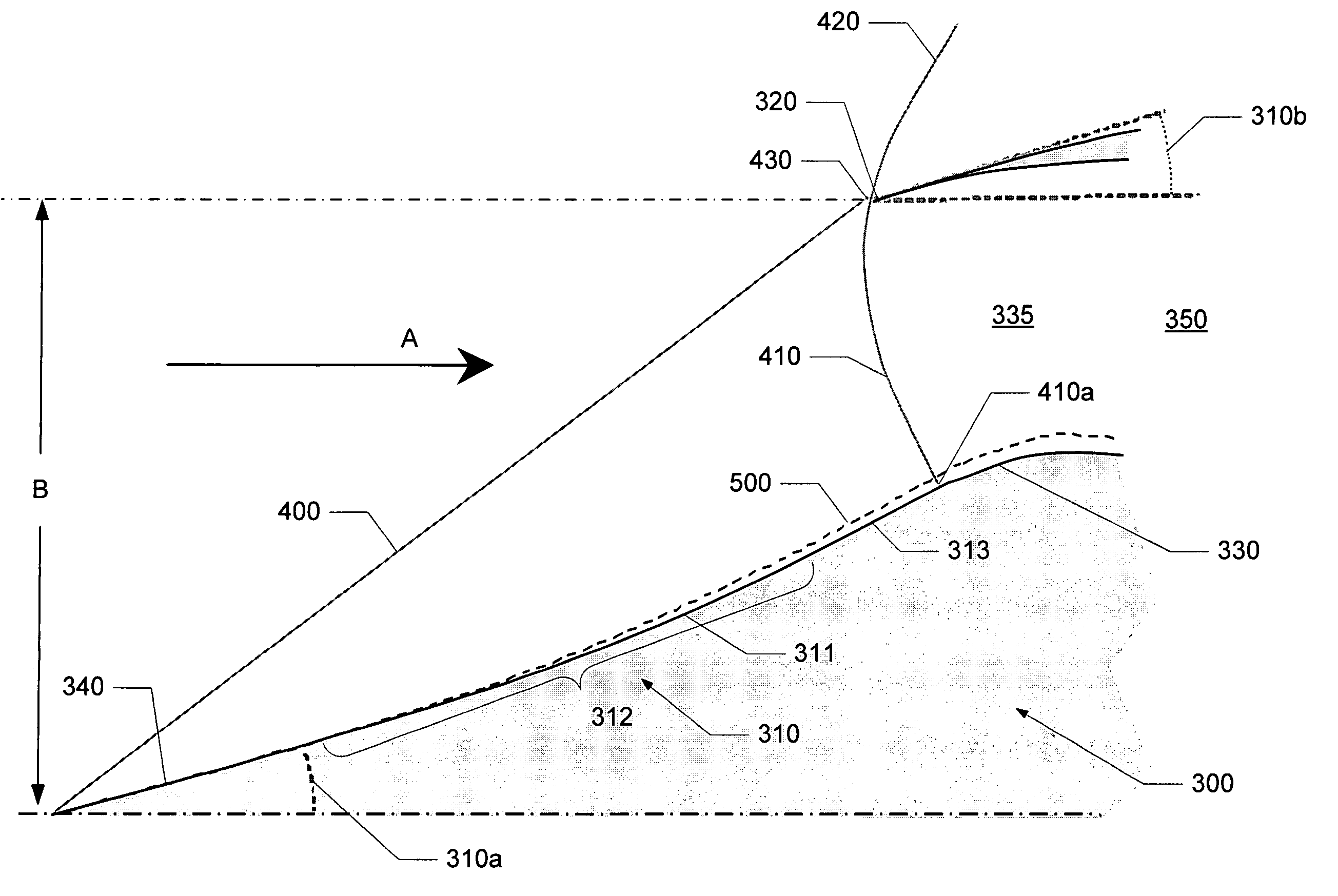
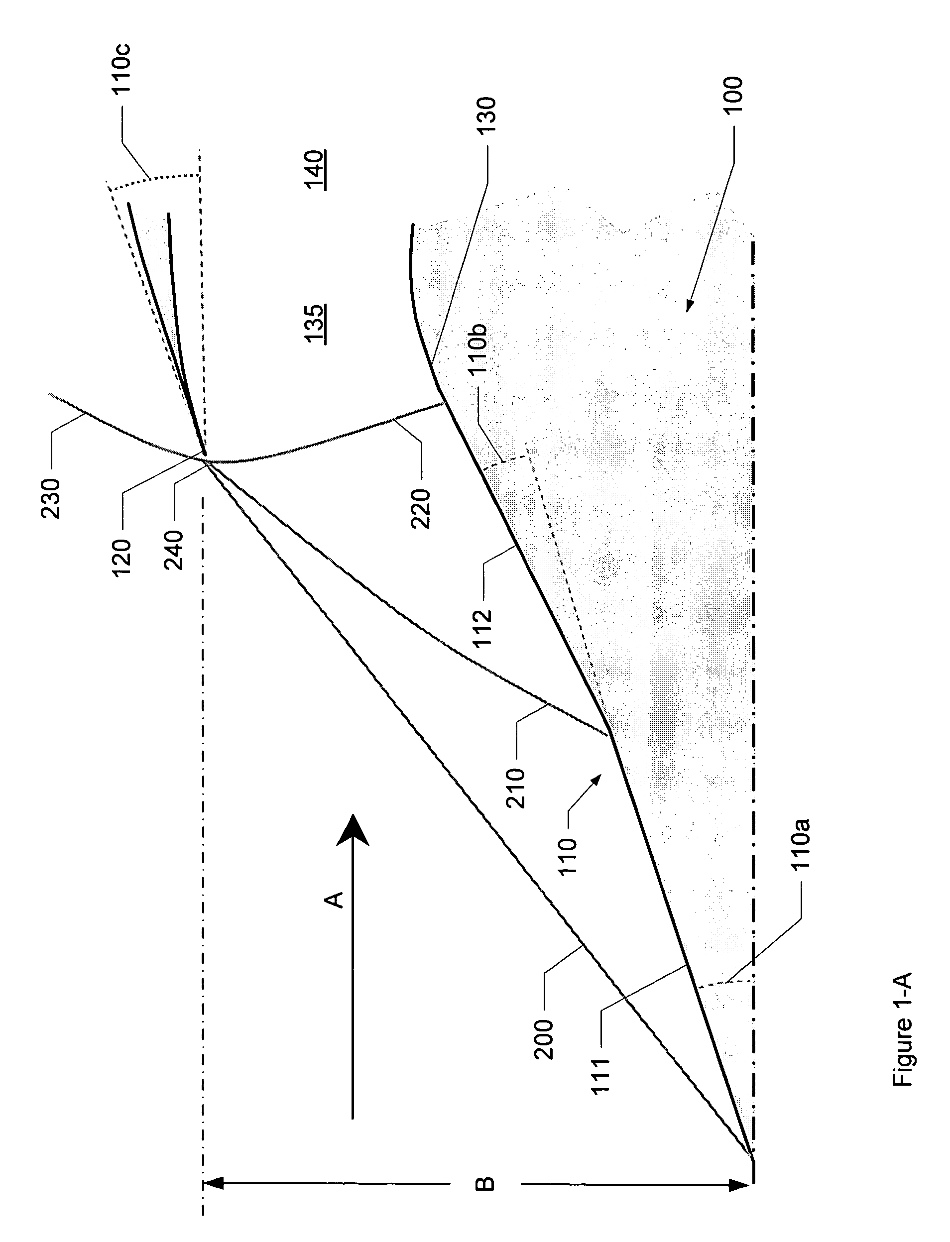
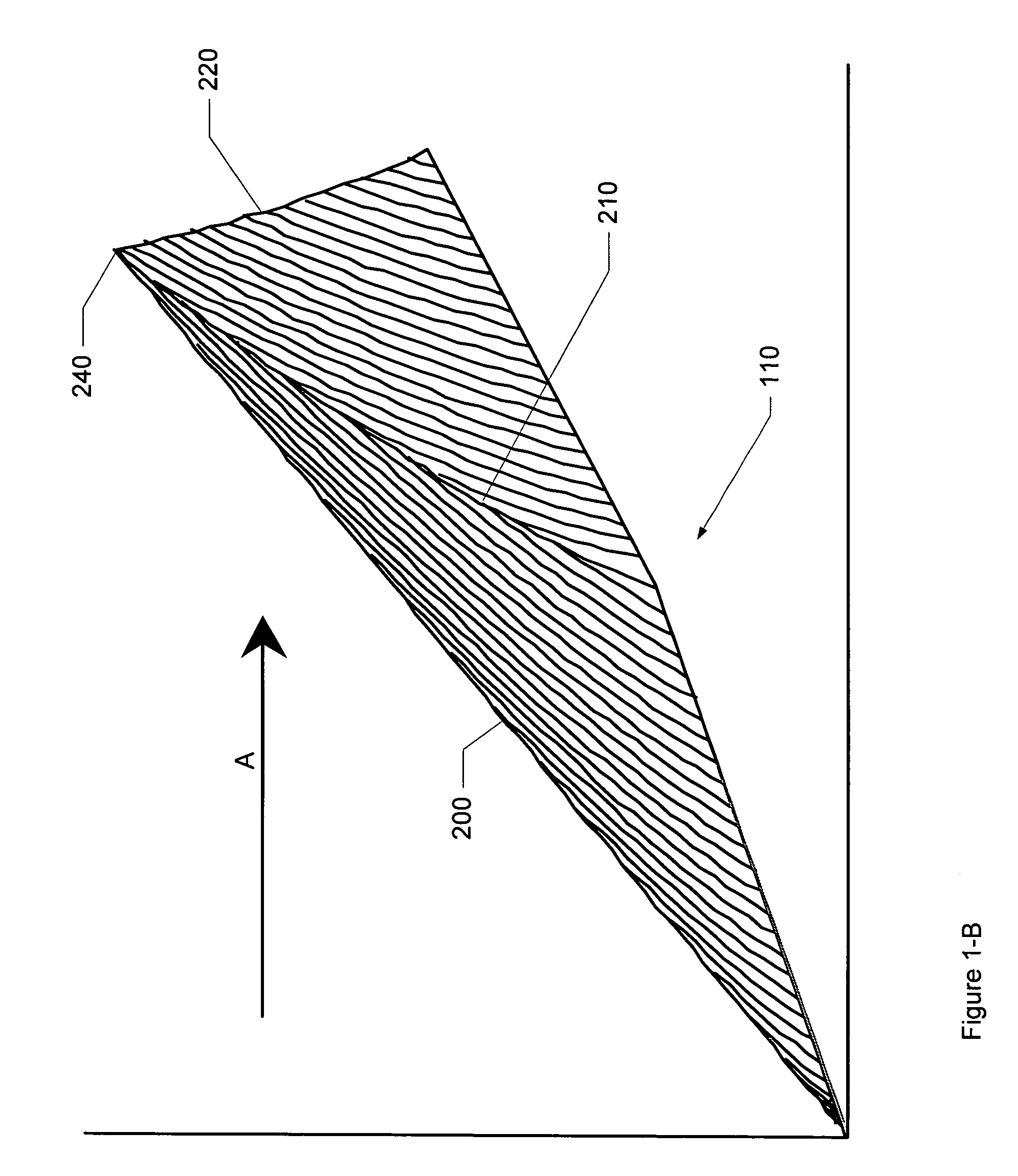
[0019]Embodiments of the invention employ a relaxed isentropic compression shaping of the compression surface of an inlet design. As used herein, the term “relaxed isentropic compression” surface refers to an isentropic compression surface characterized by a series of Mach lines in which at least a plurality of those Mach lines do not focus on the focus point where the initial shock and the terminal shock meet. This lack of Mach line focusing results in a total level of compression less than the level of compression generated by a conventional isentropic compression surface designed to the same criteria. The relaxed isentropic compression design approach may be applied to any external compression or mixed compression inlet concept, including axisymmetric, partial conic, and two-dimensional intakes. The cowling angles for external compression inlets designed with a relaxed isentropic compression surface may be reduced to approach those employed by traditional mixed compression inlets, merging the inherent shock stability robustness of external compression geometry with the high installed performance of mixed compression geometry.
[0020]To be explained more fully below, relaxed isentropic compression inlet shaping provides an increase in the design latitude for lofting the inlet cowling region while permitting control over other key inlet design parameters such as terminal shock Mach number, diffuser flow distortion, and total pressure recovery. The relaxed isentropic compression inlet shaping may also enable a reduction in cowling surface angles and, as a result, may be configured to improve inlet drag and interference drag characteristics. The reduced slope of the cowling may also lower the contribution of the inlet to the overall vehicle sonic boom characteristic during supersonic flight and decrease the potential for aerodynamic cross-interference between close-coupled inlets.

Problems solved by technology

This lack of Mach line focusing results in a total level of compression less than the level of compression generated by a conventional isentropic compression surface designed to the same criteria.
The reduced slope of the cowling may also lower the contribution of the inlet to the overall vehicle sonic boom characteristic during supersonic flight and decrease the potential for aerodynamic cross-interference between close-coupled inlets.

Method used


Image

  • Isentropic compression inlet for supersonic aircraft
  • Isentropic compression inlet for supersonic aircraft
  • Isentropic compression inlet for supersonic aircraft

Examples


Embodiment Construction

[0052]The present disclosure will now be described more fully with reference to the Figures in which various embodiments of the invention are shown. The subject matter of this disclosure may, however, be embodied in many different forms and should not be construed as being limited to the embodiments set forth herein.

[0053]Embodiments of the invention relates to supersonic inlet shaping which improves the net propulsive force through relaxed isentropic compression surfaces. As discussed above, “relaxed isentropic compression” refers to an isentropic compression surface characterized by a series of Mach lines that do not necessarily focus at the point where the initial oblique shock and the terminal shock meet. In accordance with embodiments of the invention, overall performance improvement may be accomplished using relaxed isentropic compression inlet configurations even when the inlet exhibits relatively poor total pressure recovery characteristics. Further, inlets employing relaxed...


PUM

PropertyMeasurementUnit
Lengthaaaaaaaaaa
Angleaaaaaaaaaa

Abstract

Embodiments of the invention relate to a supersonic inlet employing relaxed isentropic compression to improve net propulsive force by shaping the compression surface of the inlet. Relaxed isentropic compression shaping of the inlet compression surface functions to reduce cowl lip surface angles, thereby improving inlet drag characteristics and interference drag characteristics. Using supersonic inlets in accordance with the invention also demonstrated reductions in peak sonic boom overpressure while maintaining performance.

Description

[0001]This application claims priority to co-pending U.S. Provisional Patent Application 60 / 750,345, filed Dec. 15, 2005, and entitled “Supersonic Inlet Shaped for Dramatic Reductions in Drag and Sonic Boom Strength,” which is hereby incorporated by reference in its entirety.FIELD OF THE INVENTION[0002]The embodiments of the invention are related to supersonic inlets for supersonic aircraft and more particularly to supersonic inlet shaped to reduce drag and sonic boom strength.BACKGROUND OF THE INVENTION[0003]Many supersonic aircraft employ gas turbine engines that are capable of propelling the aircraft at supersonic speeds. These gas turbine engines, however, generally operate on subsonic flow in a range of about Mach 0.3 to 0.6 at the upstream face of the engine. The inlet decelerates the incoming airflow to a speed compatible with the requirements of the gas turbine engine. To accomplish this, a supersonic inlet is comprised of a compression surface and corresponding flow path, u...

Claims


Application Information

Patent Timeline
IPC IPC(8): F02C7/04
CPCB64D33/02B64D2033/026F02C7/04Y10T29/49323F05D2250/70F02C7/042F05D2220/80Y10T137/0318Y10T137/0536F02K7/10B64C30/00B64D27/16B64D29/00F05D2210/33
Inventor HENNE, PRESTON A.CONNERS, TIMOTHY R.HOWE, DONALD C.
Owner GULFSTREAM AEROSPACE CORP
Learn More