
Non-full pipe flow measurement method of conductive fluid

A flow measurement, conductive fluid technology, applied in the direction of fluid velocity measurement, application of electromagnetic flowmeter to detect fluid flow, volume/mass flow generated by electromagnetic effect, etc., can solve the requirement of constant fluid conductivity and other problems, to achieve a simple and reliable measurement method

Inactive Publication Date: 2008-11-12
SHANGHAI UNIV
View PDF4 Cites 26 Cited by
  • Summary
  • Abstract
  • Description
  • Claims
  • Application Information

AI Technical Summary

Problems solved by technology

For example, the multi-electrode non-full pipe electromagnetic flowmeter uses a pair of transmitting electrodes and multiple pairs of measuring electrodes, and uses the signals on different measuring electrodes to calculate the partial pipe flow at different liquid levels, so it is a multi-electrode multi-signal The measurement system of the channel has a relatively complicated structure; there is also a capacitive liquid level non-full pipe electromagnetic flowmeter, that is, a capacitive liquid level meter is combined in the electromagnetic flowmeter, which is essentially a combination method of a liquid level meter and a flow meter ; There is also a kind of non-full pipe flow measurement method based on double excitation electromagnetic flow technology, such as patents 200510028473.3, 200510110182.9 and ZL200610029236.3, etc., although this type of technology can be used under one signal channel under the condition of fluid conductivity constant Realize the measurement of partial pipe flow, but the requirement of constant fluid conductivity will limit the practical application

Method used


Image

  • Non-full pipe flow measurement method of conductive fluid
  • Non-full pipe flow measurement method of conductive fluid
  • Non-full pipe flow measurement method of conductive fluid

Examples


Embodiment Construction

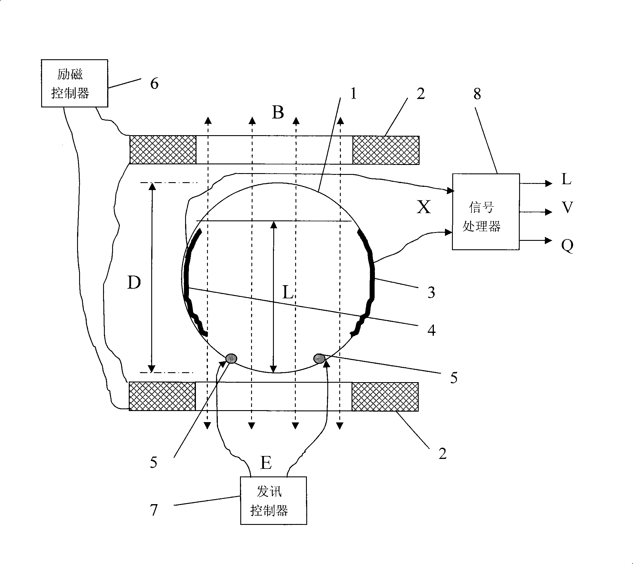
[0026] A preferred embodiment of the present invention is as follows: see figure 1 .

[0027] A method for measuring the flow rate of a conductive fluid in a partially filled pipe. The measurement setup includes a measuring tube 1 with a diameter D and an insulating inner tube wall, an excitation coil 2 outside the measuring tube 1, and measuring signals on both sides of the inner wall of the measuring tube 1. Electrode unit 3 and measuring electrode unit 4, a pair of transmitting electrodes 5 on the inner wall of measuring tube 1 lower than measuring electrode unit 3 and measuring electrode unit 4, an excitation controller 6 for controlling the magnetic field B of excitation coil 2 1. A signaling controller 7 that controls the potential E on the signaling electrode 5. There is a fluid flowing along the pipeline axis in the measuring tube 1 with a liquid level L and an average flow velocity V; it is characterized in that it only passes through the signaling electrode unit 3 an...


PUM


Abstract

The invention relates to a method for measuring the flow rate of conductive liquid in a partially filled pipe, which is characterized in that, a level detection method for the conductive liquid and a flow rate measuring method of an electromagnetic flowmeter are combined, so that the liquid level L and an average flow velocity V are obtained based on an electric potential signal X-value formed from two signal-testing electrode units and by controlling signal-transmitting electric potential and excitation, and a corresponding flow rate Q-value in a partially filled pipe is obtained; at the same time, a system structure is proposed, wherein electrode groups configurated by distributing more than two electrodes on each side of an inner wall of a measuring pipe are used as signal testing electrodes, all the electrodes of each electrode group are in parallel connection outside the measuring pipe to form an output end, so that a potential signal X is formed on the output ends of the two signal testing electrodes, thereby avoiding processing and mounting difficulty of long arc electrodes, simplifying the system structure of a multi-electrode electromagnetic flowmeter for a partially filled pipe, and improving the performance to price ratio.

Description

technical field [0001] The invention relates to a method for measuring the non-full pipe flow of conductive fluid. technical background [0002] The free surface of the fluid in the pipeline under the state of partial pipe flow makes the distribution of the fluid velocity change with the liquid level L, which makes it difficult to measure the flow. Generally, the partial pipe flow needs to measure the fluid level L first, and then calculate the average fluid velocity V of the partial pipe section according to the local flow velocity measurement value under the corresponding fluid liquid level L. [0003] The traditional partial flow measurement methods mainly include liquid level meter method, liquid level meter and flow meter combination method. The liquid level gauge method is mainly used in open channel occasions with very low accuracy requirements. The combined method of liquid level meter and flow meter is to use two instruments to measure the liquid level and flow ve...

Claims


Application Information

Patent Timeline
Patent Type & Authority Applications(China)
IPC IPC(8): G01F1/58G01F23/22G01P5/08
Inventor 李斌卫开夏江一舟张怡聪
Owner SHANGHAI UNIV
Learn More