
Position detection device for maglev vehicle and using method of device

A detection device and magnetic levitation technology, which is applied in the fields of electromagnetic wave detection, railway signal and safety, etc., can solve the problems of high construction cost and poor reliability

Active Publication Date: 2021-04-20
SOUTHWEST JIAOTONG UNIV
View PDF6 Cites 0 Cited by
  • Summary
  • Abstract
  • Description
  • Claims
  • Application Information

AI Technical Summary

Problems solved by technology

[0002] The speed measurement and positioning system is an important part of the operation control of maglev trains. At present, the main method used in the research of medium and low speed maglev trains at home and abroad is to use the through-beam photoelectric switch method or the cross loop method to detect the position information of the maglev vehicle. Both require continuous laying of equipment or facilities along the ground track, resulting in high construction costs
The through-beam photoelectric switch detection method uses a photoelectric sensor to detect the position and speed information of the magnetic levitation vehicle, which is easily disturbed by the external natural light environment and has poor reliability

Method used


Image

  • Position detection device for maglev vehicle and using method of device
  • Position detection device for maglev vehicle and using method of device
  • Position detection device for maglev vehicle and using method of device

Examples


Embodiment Construction

[0033] In order to make the purpose, technical solutions and advantages of the embodiments of the present invention clearer, the technical solutions in the embodiments of the present invention will be clearly and completely described below in conjunction with the drawings in the embodiments of the present invention. Obviously, the described embodiments It is a part of embodiments of the present invention, but not all embodiments. The components of the embodiments of the invention generally described and illustrated in the figures herein may be arranged and designed in a variety of different configurations. Accordingly, the following detailed description of the embodiments of the invention provided in the accompanying drawings is not intended to limit the scope of the claimed invention, but merely represents selected embodiments of the invention. Based on the embodiments of the present invention, all other embodiments obtained by persons of ordinary skill in the art without cre...


PUM


Abstract

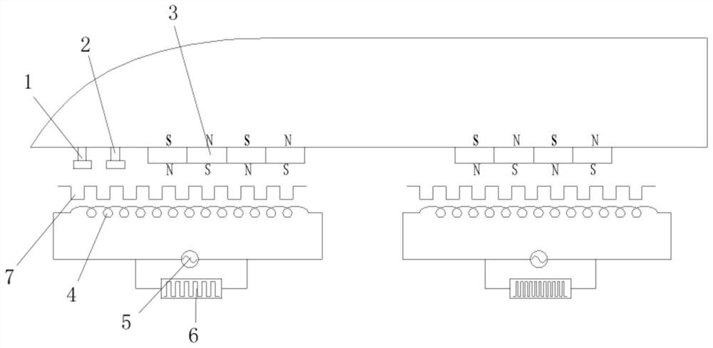
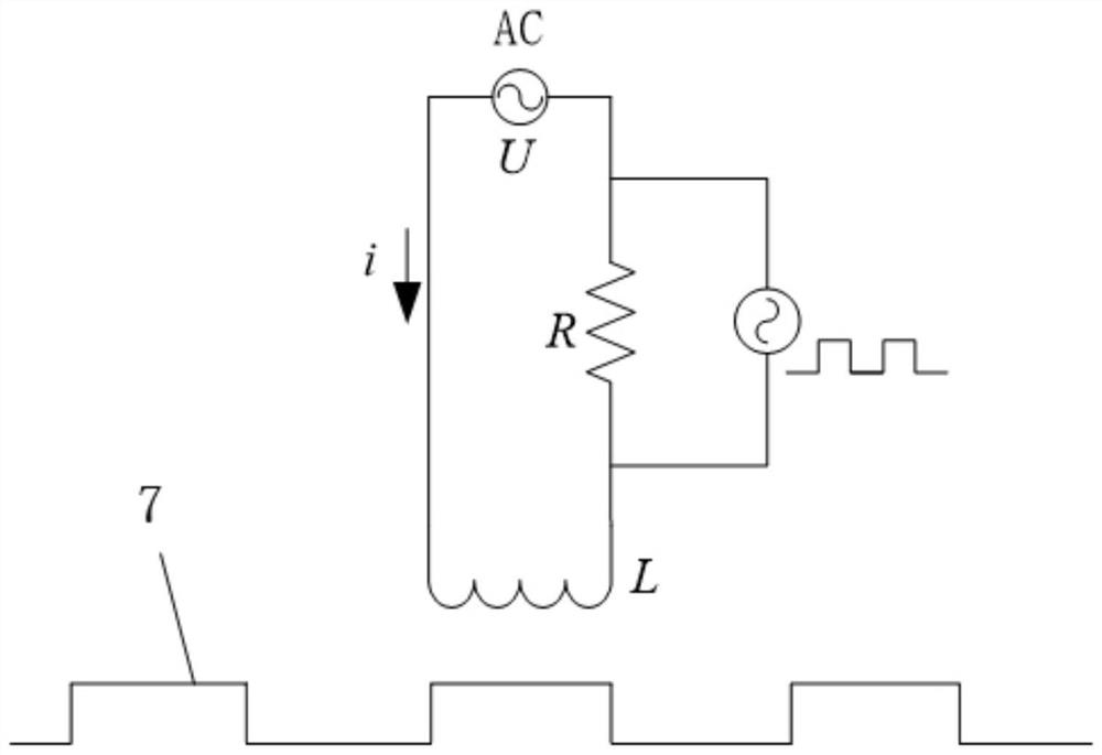
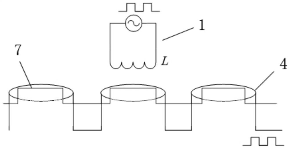
The invention relates to a position detection device for a maglev vehicle. The position detection device comprises a carrier signal probe, an iron core pulse probe and a vehicle-mounted rotor which are arranged on the maglev vehicle, and multiple sections of measurement assemblies which are sequentially arranged along a ground track. Each section of measuring assembly comprises a stator coil arranged on the track, a traction driving power supply connected with the stator coil in series, a carrier wave generating device connected with the traction driving power supply in parallel and matched with the carrier wave signal probe, and a stator iron core matched with the iron core pulse probe. The vehicle-mounted rotor is matched with the stator coil to drive the maglev vehicle to suspend and move. The device is simple in structure, reasonable in design, capable of being arranged in a segmented mode, capable of reducing cost, quite easy to operate and calculate when used for detecting the position of the maglev vehicle and high in measuring precision.

Description

technical field [0001] The invention relates to the field of maglev trains, in particular to a position detection device for maglev vehicles and a method for using the same. Background technique [0002] The speed measurement and positioning system is an important part of the operation control of maglev trains. At present, the main method used in the research of medium and low speed maglev trains at home and abroad is to use the through-beam photoelectric switch method or the cross loop method to detect the position information of the maglev vehicle. Both need to continuously lay equipment or facilities along the ground track, and the construction cost is high. The through-beam photoelectric switch detection method uses a photoelectric sensor to detect the position and speed information of the maglev vehicle, which is easily disturbed by the external natural light environment and has poor reliability. Contents of the invention [0003] The purpose of the present invention...

Claims


Application Information

Patent Timeline
IPC IPC(8): B61L25/02G01V3/12
Inventor 张卫华张江华邓自刚
Owner SOUTHWEST JIAOTONG UNIV
Learn More