
Scroll fluid machine

A fluid machinery and scroll technology, applied in the direction of rotary piston machinery, rotary piston engines, mechanical equipment, etc., can solve the problems of complex processing procedures, poor compression efficiency, long processing time, etc., to shorten processing time and improve Compression efficiency, simple shape effect

Inactive Publication Date: 2008-10-29
HITACHI LTD
View PDF3 Cites 2 Cited by
  • Summary
  • Abstract
  • Description
  • Claims
  • Application Information

AI Technical Summary

Problems solved by technology

Therefore, the air accumulated in the concave portion is not compressed, but leaks to the low-pressure side after passing through the peripheral surface of the opposing overlapped portion, resulting in poor compression efficiency.
[0009] In addition, since the protrusions are provided on the peripheral surface of the overlapping portion composed of curved surfaces, it is necessary for a processing tool such as an end mill to reciprocate in the radial direction in cooperation with the protrusions, so there is a tendency for machining errors to easily occur.
In addition, since the processing steps are complicated, the processing time is long and the productivity is low.

Method used


Image

  • Scroll fluid machine
  • Scroll fluid machine
  • Scroll fluid machine

Examples


no. 5 approach

[0142] Next, FIG. 15 shows a fifth embodiment of the present invention, and this embodiment is characterized in that an involute curved portion following the involute is provided on the outer diameter side of the overlapping portion. In addition, in this embodiment, the same code|symbol is attached|subjected to the component element as said 1st Embodiment, and the description is abbreviate|omitted.

[0143] Reference numeral 61 denotes a fixed scroll of a scroll air compressor, and the fixed scroll 61 is composed of an end plate 62, an overlapping portion 63, a cylindrical portion 64, a flange portion (not shown) and the like in substantially the same manner as in the first embodiment. constitute. Furthermore, the overlapping portion 63 is formed in a spiral shape having an inner peripheral surface 63A and an outer peripheral surface 63B.

[0144] However, on the outer peripheral surface 63B of the overlapping portion 63, a plurality of closest portions 65 and a flat surface ...


PUM


Abstract

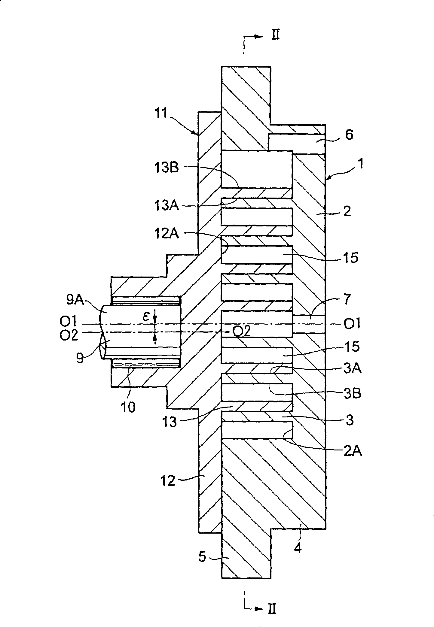
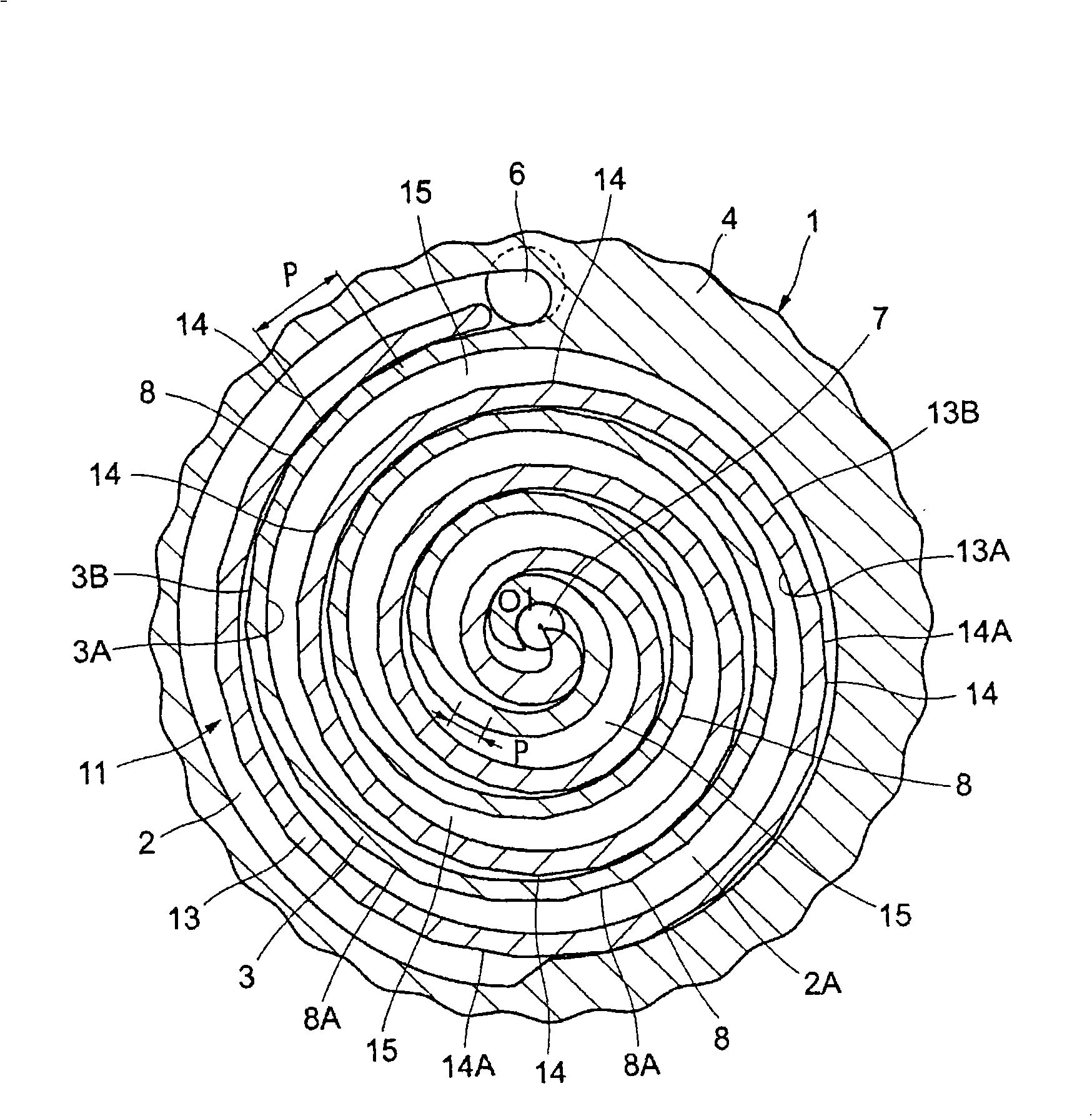
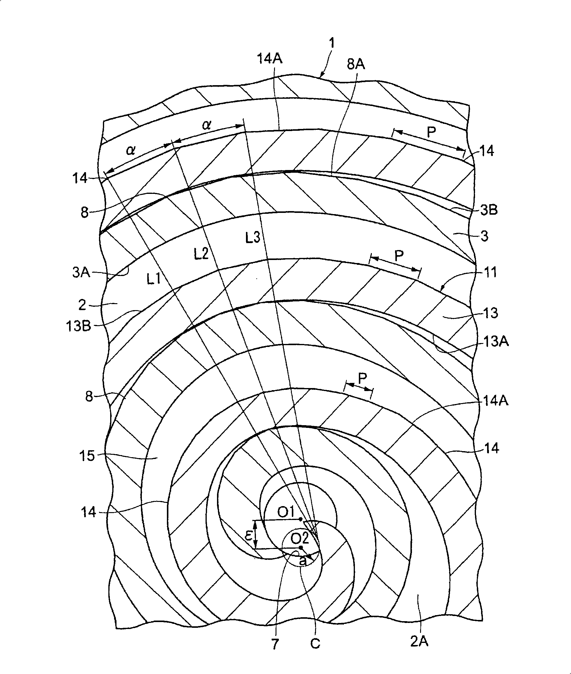
The present invention relates to a scroll fluid machine, wherein, a gap between opposing wrap portions is narrowed to increase compression efficiency, and an amount of machining time is reduced to thereby increase productivity. A plurality of proximate portions 8 are formed, at spacings in a spiral direction, on an outer peripheral surface 3 B of a wrap portion 3 of a fixed scroll 1. Flat surfaces 8 A are used to connect adjacent proximate portions 8. Similarly, a plurality of proximate portions 14 are formed, at spacings in the spiral direction, on an outer peripheral surface 13 B of a wrap portion 13 of an orbiting scroll 11. Flat surfaces 14 A are used to connect adjacent proximate portions 14. In this way, the outer peripheral surfaces 3 B and 13 B of the wrap portions 3 and 13 can be formed in polyangular shapes, so as to reduce a gap between the wrap portions 3 and 13 and simplify the shapes. As a result, an amount of machining time can be reduced.

Description

technical field [0001] The present invention relates to a scroll type fluid machine suitable for use in, for example, air compressors, vacuum pumps and the like. Background technique [0002] Generally, a scroll-type fluid machine is configured including a fixed scroll and an orbiting scroll provided to face the fixed scroll. In addition, the fixed scroll and the orbiting scroll each have a disc-shaped end plate and are vertically provided on the end plate in the axial direction so as to spirally wrap from the inner diameter side toward the outer diameter side of the end plate. the overlapping portion. Accordingly, the fixed scroll and the orbiting scroll are divided into a plurality of compression chambers by overlapping overlapping portions. [0003] In addition, since the scroll fluid machine rotates the orbiting scroll with a certain radius of rotation relative to the fixed scroll through the drive shaft, the gas can be sucked in from the suction port provided on the o...

Claims


Application Information

Patent Timeline
Patent Type & Authority Applications(China)
IPC IPC(8): F04C18/02F04C25/02F04C29/00
CPCF04C2230/10F01C1/0215F01C1/0246
Inventor 兼本喜之
Owner HITACHI LTD
Learn More