
Coding and decoding method for down-hole information transmission

An encoding method and information transmission technology, which are applied to the processing and self-checking of combined pulse encoding, and the encoding and decoding fields of downhole information transmission, can solve the problems of sacrificing transmission efficiency, intermediate pulse positioning error, and high noise, and improve the resistance to Effects of Interference Ability

Inactive Publication Date: 2008-10-22
CNPC DRILLING RES INST
View PDF5 Cites 12 Cited by
  • Summary
  • Abstract
  • Description
  • Claims
  • Application Information

AI Technical Summary

Problems solved by technology

[0005] Although the above-mentioned combined pulse code has certain anti-interference ability, in many cases, due to channel deterioration, high noise, and combined coded pulse distortion, the decoder cannot accurately locate the real pulse position, resulting in decoding errors
[0006] In this regard, special treatment, such as increasing the width of a single time slot, can improve the anti-interference ability, but it is at the expense of greatly sacrificing transmission efficiency
And although some bit errors can be detected by adding parity bits, the traditional parity check method applied to binary bit streams is not very suitable for the above coding methods
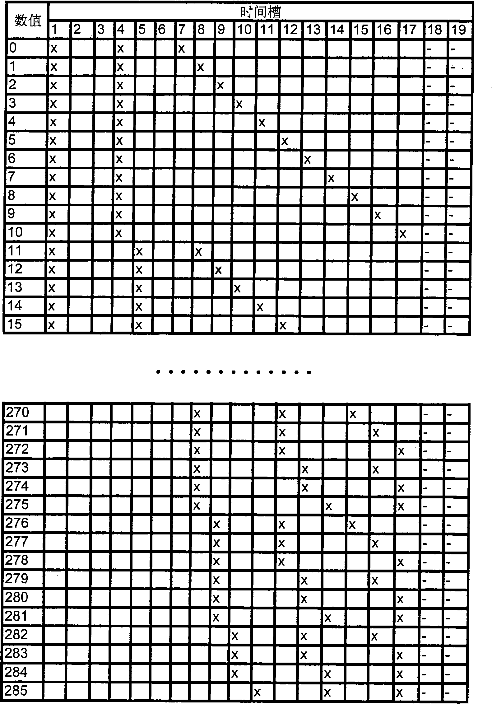
[0007] For example in figure 1 Among them, the combined encoding of the value 1 (bit stream 00000001) and the value 11 (bit stream 00001011) only has a difference of 1 slot in the middle pulse. If the positioning error of the middle pulse is caused by signal interference, the real value 1 will be decoded as a value The possibility of 11, at this time, because the number of 1 in the binary bit stream of the two values ​​is odd, the traditional 1-bit parity check cannot detect this error

Method used


Image

  • Coding and decoding method for down-hole information transmission
  • Coding and decoding method for down-hole information transmission
  • Coding and decoding method for down-hole information transmission

Examples


Embodiment 1

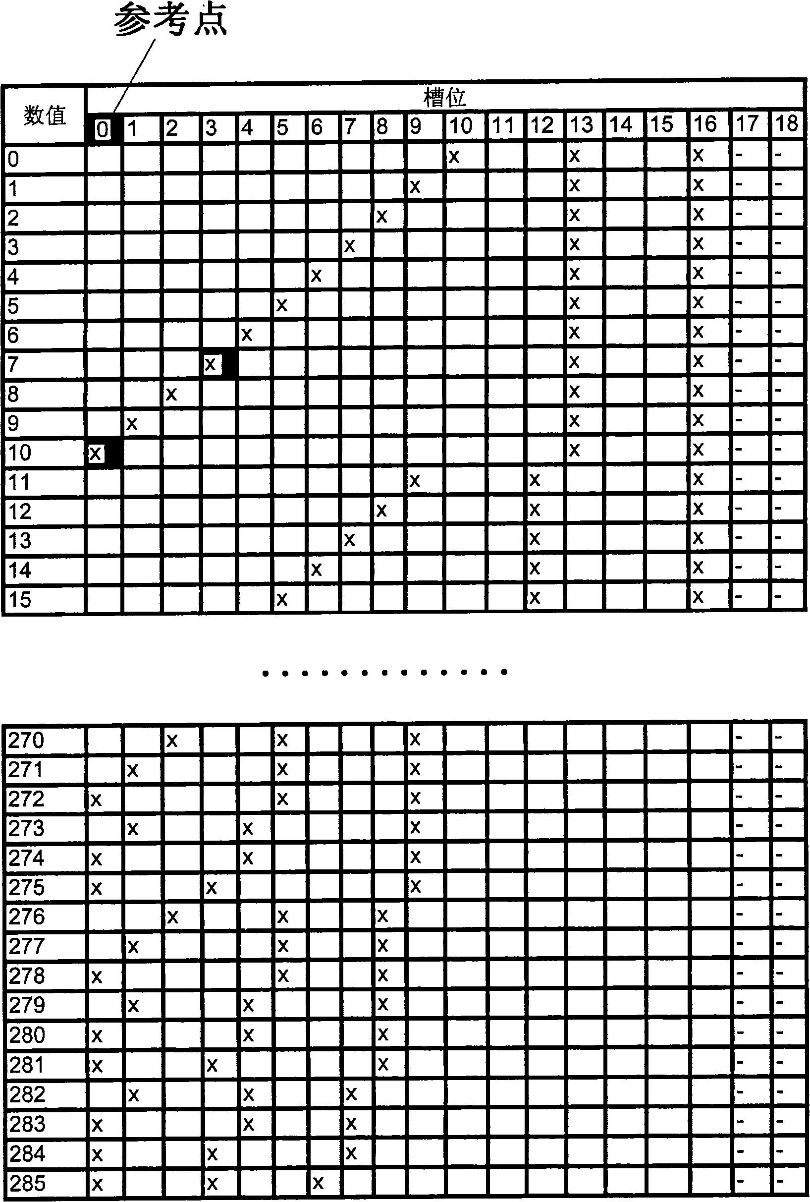
[0031] Figure 2A What is shown is a schematic diagram of a group of combined coding mapping data in the coding of downhole information transmission in Embodiment 1 of the present invention. Wherein, the low-order pulse code bits and high-order pulse code bits in each coding unit in the above-mentioned combined coding mapping data are arranged in a certain order; then, the reference point is selected in the coding unit so that the above-mentioned The code bit of the low-order pulse comes first, and the code bit of the above-mentioned high-order pulse follows (such as Figure 2A shown); the position of the above-mentioned low-order pulse code bit is even-numbered relative to the above-mentioned reference point.

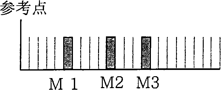
[0032] Figure 2B , Figure 2C What is shown is a schematic diagram of the selection of the reference point for positioning the low-order pulse of the combined code, that is, the selected reference point is different according to the selection of different combined ...


PUM


Abstract

The present invention provides a method for coding and decoding information transmitted underground. The coding method comprises the following steps of: obtaining a set of combined coding mapping data, arranging the low-position pulse code position and the high-position pulse code position in each coding unit of the combined coding mapping data in a certain sequence; selecting a reference point in the coding unit, the low-position pulse code position being closer to the reference point than the high-position pulse code position; and carrying out even processing on the position of the low-position pulse code position corresponding to the reference point. The method can improve the anti-interference capacity of the low-position pulse code position modulation by 1 time; the high-position pulse taking the low-position pulse position as reference can eliminate the fuzzy of a part of reference points, thereby indirectly improving the anti-interference capacity of the high-position pulse code position modulation.

Description

technical field [0001] The present invention relates to the coding processing method used for downhole information telemetry transmission in oil and natural gas drilling operation measurement while drilling or logging while drilling, especially relates to the processing and self-verification of combined pulse coding, specifically a A coding and decoding method for downhole information transmission. Background technique [0002] In oil and gas drilling operations, it is often necessary to transmit the measurement information at the bottom of the well to the ground in time through the fluid channel of the circulation system. Since the transmission distance may range from hundreds of meters to more than ten kilometers, and the channel environment is extremely harsh, the available channel bandwidth It is very narrow, and the passband frequency is very low, so the information transmission speed is very low. These factors make many advanced technologies in the traditional communic...

Claims


Application Information

Patent Timeline
Patent Type & Authority Applications(China)
IPC IPC(8): H03M13/09E21B47/12
Inventor 王家进邓乐
Owner CNPC DRILLING RES INST
Learn More