
Antenna having ultra-wideband and multiple rejection band based on bimodule and double rejection band filter

A technology of ultra-wideband antenna and double stop band, which is applied in the direction of antenna, electrical components, radiation element structure, etc., can solve problems such as not easy to design stop band filter, reduce cavity volume, large power capacity, etc., to achieve Good stop band suppression effect, good application prospect and low processing cost

Inactive Publication Date: 2012-04-25
SOUTHEAST UNIV
View PDF4 Cites 0 Cited by
  • Summary
  • Abstract
  • Description
  • Claims
  • Application Information

AI Technical Summary

Problems solved by technology

Compared with microstrip transmission lines, half-mode substrate integrated waveguide (HMSIW) has a higher quality factor, low loss, large power capacity, and can be well integrated with planar systems. Compared with substrate integrated waveguide ( SIW) further reduces the volume of the cavity, they can be realized by ordinary single-layer PCB technology, which is easy to process, but it is not easy to combine with microstrip to design a stop band filter

Method used


Image

  • Antenna having ultra-wideband and multiple rejection band based on bimodule and double rejection band filter
  • Antenna having ultra-wideband and multiple rejection band based on bimodule and double rejection band filter
  • Antenna having ultra-wideband and multiple rejection band based on bimodule and double rejection band filter

Examples


Embodiment Construction

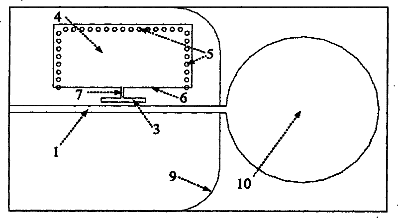
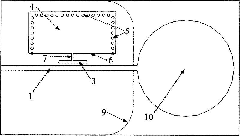
[0021] The dual-mode, double-stop band filter consists of a dielectric substrate, metal copper foils coated on the upper and lower sides of the dielectric substrate, and metallized through holes 5 connecting the copper foils. The energy is mainly transmitted through the 50 ohm microstrip feeder 1, and the microstrip coupling line 3 is provided on the side of the microstrip feeder 1, and the coupling line 3 is connected to the substrate integrated half-mode cavity 4 through the microstrip line 7. The half-mold cavity 4 is composed of a half-mold cavity patch 6, a metallized through hole 5 and a metal ground 9, and its three sides are all composed of metallized through holes 5, which can be equivalent to an electric wall, and the other side is an open structure , which can be approximated as a magnetic wall. The microstrip line 7 is connected to the center of the coupled microstrip line 3 from the center of the open boundary of the half-mode cavity 4 . The coupled microstrip li...


PUM


Abstract

The invention discloses a multi-stop band and ultra-wideband antenna technique based on the dual-mode and dual-stop band filters, which relates to an ultra-wideband antenna technique applicable to short distance wireless communication and data transmission. The multi-stop band and ultra-wideband antenna technique based on the dual-mode and dual-stop band filters can effectively solve the interference problems in the wideband communication system caused by the signals from the existing narrowband communication systems. The multi-stop band and ultra-wideband antenna technique based on the dual-mode and dual-stop band filters adopts the technique of dual-mode and dual-stop band filters, which realizes the technique of single-layered plane electric circuit, and is particularly suitable for the ultra-wideband communication systems in need of suppressing a plurality of interferences. The multi-stop band and ultra-wideband antenna is designed on the basis of techniques such as the dual-mode and dual-stop band filters and the disk aerials. The dual-stop band filter consists of a coupled microstrip line and a half mode substrate-integrated waveguide cavity; the coupled microstrip line and the half mode substrate-integrated waveguide cavity correspond to a resonant mode respectively so as to provide two stop bands. Realized by the general technique of single-layered PCB boards, the multi-stop band and ultra-wideband antenna based on the dual-mode and dual-stop band filters has the advantages of simple design and processing, high integration, nice suppression of the stop bands and bright application prospect in the ultra-wideband communication systems.

Description

technical field [0001] The invention relates to an ultra-wideband antenna technology applicable to short-distance wireless communication and data transmission. The antenna can effectively solve the problem that the broadband communication system is interfered by other existing narrowband communication system signals. It adopts a dual-mode dual-stop-band filter technology, which can be realized by using single-layer planar printed circuit technology, and is especially suitable for ultra-wideband communication systems that need to suppress multiple interferences. Background technique [0002] Ultra-wideband communication system has a good application prospect in short-distance wireless access and high-speed data transmission. It has made great progress in recent years, but its wide application still faces many practical problems that need to be solved. One of the important difficulties is how to deal with interference from other communication or adjacent radio frequency system...

Claims


Application Information

Patent Timeline
Patent Type & Authority Patents(China)
IPC IPC(8): H01Q1/38H01Q13/08
Inventor 董元旦洪伟
Owner SOUTHEAST UNIV
Learn More