
Optical fibre Sagnac loop dynamic weighing sensor

A technology of dynamic weighing and optical fiber circulator, which is applied in the direction of instruments, weighing, measuring devices, etc., can solve the problems of large sensing mechanism, slow test response, low test accuracy, etc., and achieve the expansion of measurement field, sensitivity and accuracy Improve the effect of low device cost

Inactive Publication Date: 2008-10-15
SHANGHAI INST OF OPTICS & FINE MECHANICS CHINESE ACAD OF SCI
View PDF0 Cites 15 Cited by
  • Summary
  • Abstract
  • Description
  • Claims
  • Application Information

AI Technical Summary

Problems solved by technology

my country’s dynamic weighing of vehicles started relatively late, starting in the early 1980s, and the research institute was earlier in Chongqing Highway Research Institute. At present, there are more than 20 related units in China engaged in research in this area. Since the systems developed in China are all Traditional dynamic weighing technology is adopted, so there are inherent defects: slow test response, low test accuracy and huge sensing mechanism, etc.
The disadvantage of this technology is that it needs a good wavelength demodulation technology, the system cost is high, and it is necessary to minimize the influence of the temperature-sensitive characteristics of the fiber Bragg grating on the dynamic pressure measurement.

Method used


Image

  • Optical fibre Sagnac loop dynamic weighing sensor
  • Optical fibre Sagnac loop dynamic weighing sensor
  • Optical fibre Sagnac loop dynamic weighing sensor

Examples


Embodiment Construction

[0026] The present invention will be further described below in conjunction with the embodiments and accompanying drawings.

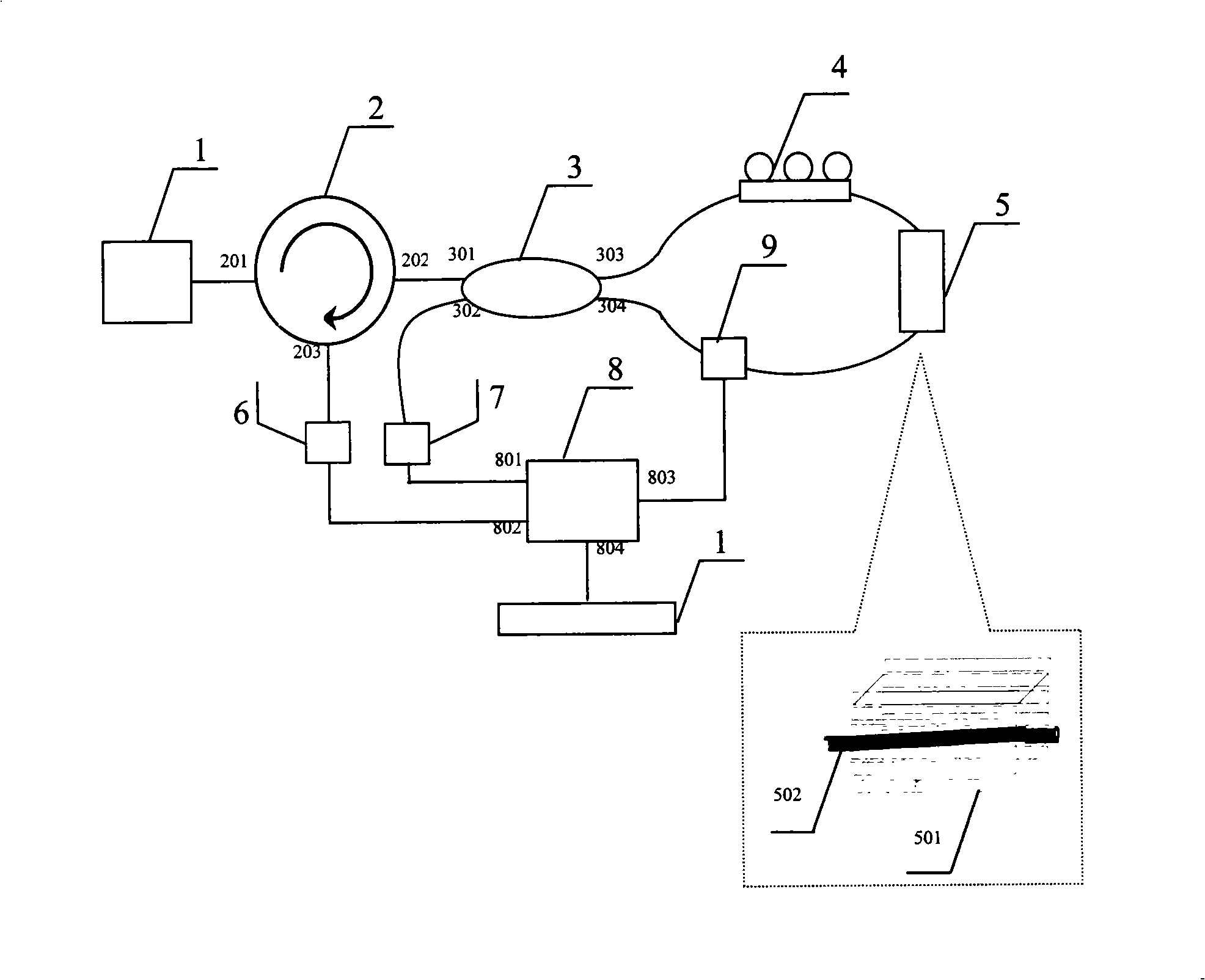
[0027] see first figure 1 , figure 1 It is a structural schematic diagram of an optical fiber Sagnac ring dynamic weighing sensor of the present invention. The optical fiber Sagnac ring circuit dynamic weighing sensor of the present invention includes a light source module 1 with a pigtail output, an optical fiber circulator 2, an optical fiber coupler 3, and an optical fiber polarization controller 4 , Fiber protection enhanced sensor head 5, first photoelectric detection unit 6, second photoelectric detection unit 7, data acquisition card 8, piezoelectric ceramic actuator 9, signal processing and display system 10. The light source module 1 is connected to the port 201 of the optical fiber circulator 2 . The second port 202 of the optical fiber circulator 2 is connected to the first port 301 of the optical fiber coupler 3 through an optical fiber. ...


PUM


Abstract

The invention relates to a fiber Sagner loop dynamic weighing sensor. In the sensor, a tail fiber of a light source module is connected with a first port of a fiber circulator; a second port of the fiber circulator is connected with a first port of a fiber coupler; a third port and a fourth port of the fiber coupler are connected to form a loop circuit by fibers; a fiber polarization controller, a fiber protection and enhancement sensing head and a piezoceramics actuator are connected in series to the loop circuit; a third port of the fiber circulator is connected with an input terminal of a first photodetection unit; a second port of the fiber coupler is connected with an input terminal of a second photodetection unit; an output terminal of the first photodetection unit is connected with a data acquisition card; an output terminal of the second photodetection unit is connected with the data acquisition card; the data acquisition card is connected with an input terminal of the piezoceramics actuator to form a feedback loop and connected with a signal processing and displaying system. The fiber Sagner loop dynamic weighing sensor has the characteristics of strong environmental intrusion resisting capacity, high measuring precision and accuracy and wide measuring scope.

Description

technical field [0001] The invention relates to an optical fiber dynamic weighing sensor, in particular to an optical fiber Sagnac ring (hereinafter referred to as Sagnac ring) dynamic weighing sensor. Background technique [0002] In recent years, the phenomenon of over-limit and overloading of road transport vehicles in our country is very common. In severe areas, almost all freight vehicles have over-limit and overloading behaviors to varying degrees. The over-limit and overloaded transportation of vehicles has caused great harm to traffic safety, transportation market, vehicle production order and road and bridge infrastructure. [0003] At present, there are two main types of road vehicle weighing: static weighing and dynamic weighing. Static weighing means that road management personnel let suspected overweight vehicles enter a fixed weighing station for weighing. This is the most accurate method for vehicle weighing, but this method is inefficient and easy to cause t...

Claims


Application Information

Patent Timeline
Patent Type & Authority Applications(China)
IPC IPC(8): G01G19/03G01G9/00
Inventor 甘久林蔡海文耿健新潘政清方祖捷瞿荣辉
Owner SHANGHAI INST OF OPTICS & FINE MECHANICS CHINESE ACAD OF SCI
Learn More