Laser image formation device
一种激光、图像的技术,应用在激光器、放映装置、图像通信等方向,能够解决变化、影像劣化明亮度等问题,达到减少数量的效果
- Summary
- Abstract
- Description
- Claims
- Application Information
AI Technical Summary
Problems solved by technology
Method used
Image

Examples
Embodiment approach 1
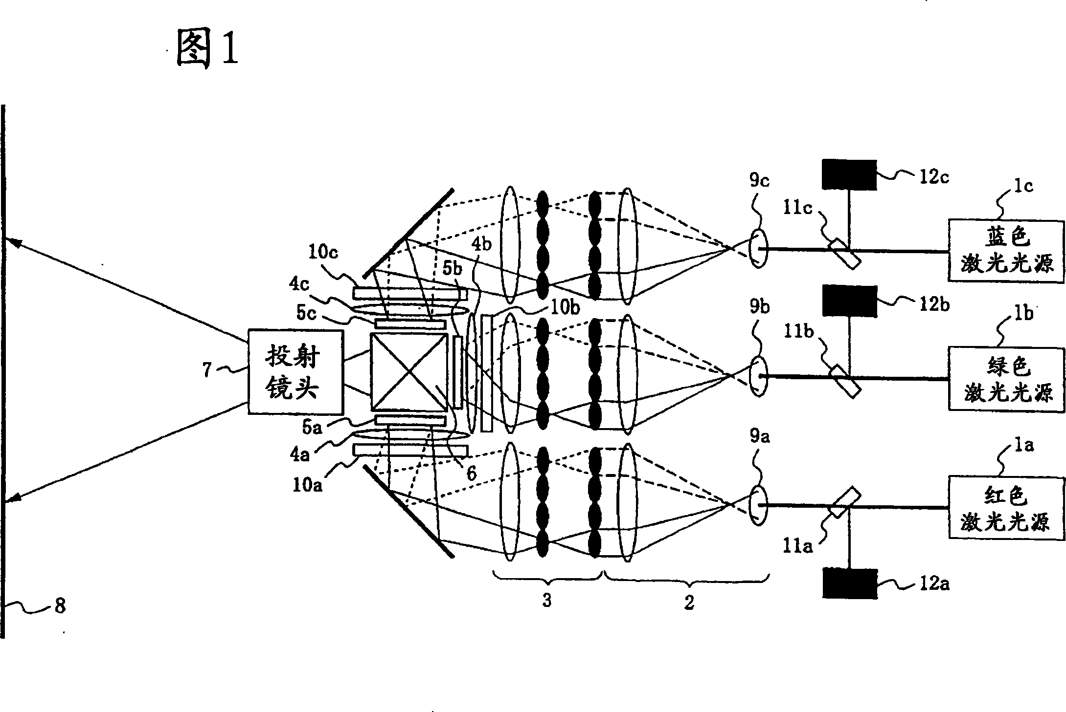
[0088] figure 1 A schematic configuration diagram of the laser image forming apparatus according to Embodiment 1 of the present invention is shown.
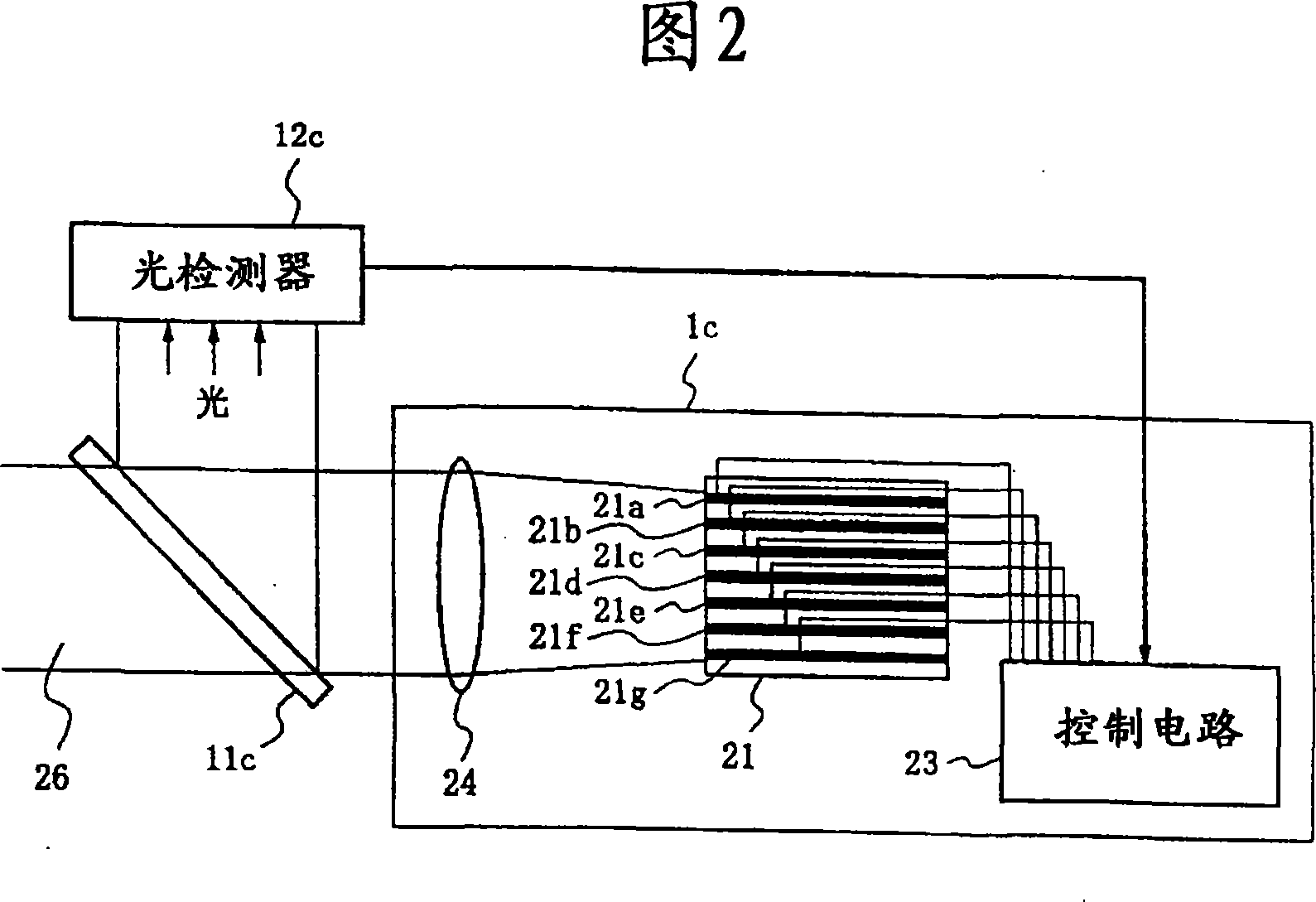
[0089] exist figure 1 Among them, for the laser light emitted from the red laser light source 1a, the green laser light source 1b, and the blue laser light source 1c, it is converged by the condenser lenses 9a, 9b, 9c, and passed through the expander optical system 2 and the integrator optical system (uniform illumination ) 3, perform beam shaping to obtain a uniform light intensity distribution, and irradiate the diffuser plates 10a, 10b, and 10c in order to remove speckle noise. The laser light diffused by the diffusion plates 10a to 10c illuminates the spatial light modulators 5a, 5b, and 5c formed of, for example, liquid crystal panels to form a two-dimensional image. The light passing through the spatial light modulation elements 5 a , 5 b , and 5 c is synthesized by a dichroic prism 6 and projected onto a screen 8 throu...
Embodiment approach 2
[0119] In the laser image forming apparatus according to Embodiment 2 of the present invention, in order to reduce the burden imposed on the laser light emitting unit by always performing laser output detection in Embodiment 1, a laser light is generated in one of the laser light emitting units of each laser light source. In case of abnormality / failure, laser output detection is performed.
[0120] In the laser image forming apparatus according to Embodiment 2, a predetermined laser drive current value is set in advance in each stripe of the multi-stripe semiconductor laser, and when the drive current of each stripe exceeds the set predetermined laser drive current value, In this case, the output of laser light is detected.
[0121] In the laser image forming apparatus according to the second embodiment, the difference from the first embodiment is the optical system of the laser light sources 1a, 1b, and 1c of the respective colors, and only the different parts will be describ...
Embodiment approach 3
[0142] In the laser image forming apparatus according to Embodiment 3 of the present invention, image formation is performed by emitting laser light from each laser light source in a field sequential manner using one spatial light modulation element. In this laser image forming apparatus, according to Field-sequential emission timing detects the output of laser light sources of colors that are not displayed, so that the degradation status of each laser light source can be grasped at the same time while providing clear images without brightness changes and image degradation.
[0143] Figure 7 A schematic configuration diagram of a laser image forming apparatus according to Embodiment 3 of the present invention is shown. for with figure 1 The same reference numerals are used for the same parts, and descriptions thereof are omitted.
[0144] exist Figure 7 Among them, the light emitted from the red laser light source 1a, the green laser light source 1b, and the blue laser l...
PUM
 Abstract
Description
Claims
Application Information
 - R&D
- Intellectual Property
- Life Sciences
- Materials
- Tech Scout
- Unparalleled Data Quality
- Higher Quality Content
- 60% Fewer Hallucinations
Browse by: Latest US Patents, China's latest patents, Technical Efficacy Thesaurus, Application Domain, Technology Topic, Popular Technical Reports.
© 2025 PatSnap. All rights reserved.Legal|Privacy policy|Modern Slavery Act Transparency Statement|Sitemap|About US| Contact US: help@patsnap.com