
Magnetic rheologic pilot-operated reversing valve for hydraulic support

A technology of electro-hydraulic control reversing valve and magneto-rheological valve, which is applied in the direction of mine roof support, pillar/support, mining equipment, etc., and can solve the problem that the solenoid valve does not meet the explosion-proof performance requirements, the servo valve cannot work normally, and cannot be guaranteed to use and other problems, to achieve the effect of simple manufacturing process, simple structure and low cost

Inactive Publication Date: 2011-04-27
黑龙江科大科技开发有限公司
View PDF0 Cites 2 Cited by
  • Summary
  • Abstract
  • Description
  • Claims
  • Application Information

AI Technical Summary

Problems solved by technology

As the core component of the hydraulic control system, the traditional hydraulic valve has problems such as moving mechanical parts, complex structure, high processing requirements, easy wear, and high cost. Moreover, the oil in these servo valves has to flow through many small gaps, which are harmful to the oil. The dirt in the liquid is very sensitive, and it is easy to cause the servo valve to fail to work normally due to oil dirt.
[0003] With the development of my country's coal industry, the degree of mechanization of coal mining equipment is also developing rapidly. The computer automatic control system of hydraulic support is being used more and more in major mining bureaus. The key component of domestic hydraulic support is the electro-hydraulic control reversing valve. Due to many reasons, it cannot be applied. Solenoid valves used in other industries do not meet the requirements of explosion-proof performance and cannot be used in the harsh working environment of coal mines.

Method used


Image

  • Magnetic rheologic pilot-operated reversing valve for hydraulic support
  • Magnetic rheologic pilot-operated reversing valve for hydraulic support
  • Magnetic rheologic pilot-operated reversing valve for hydraulic support

Examples


Embodiment Construction

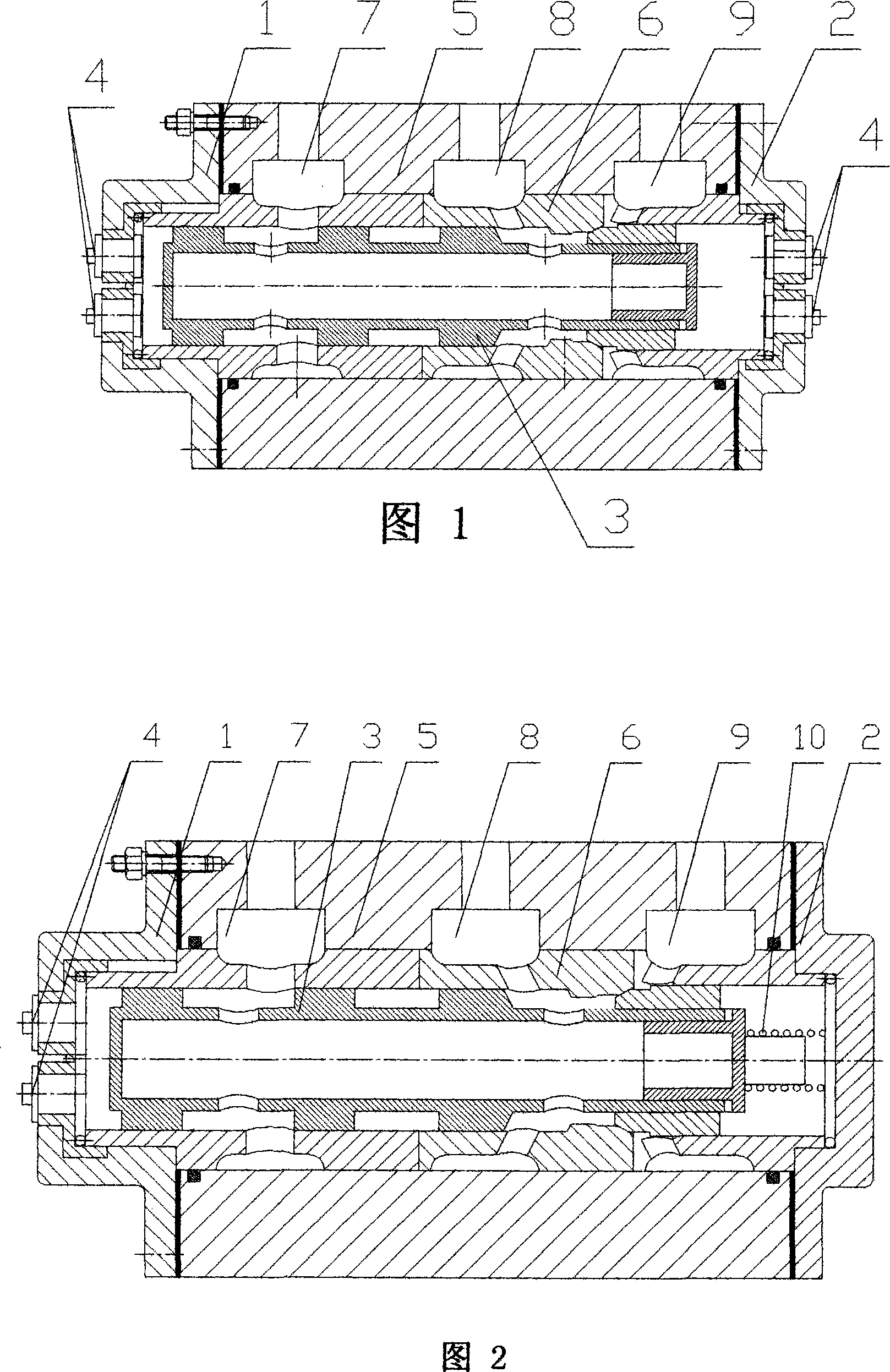
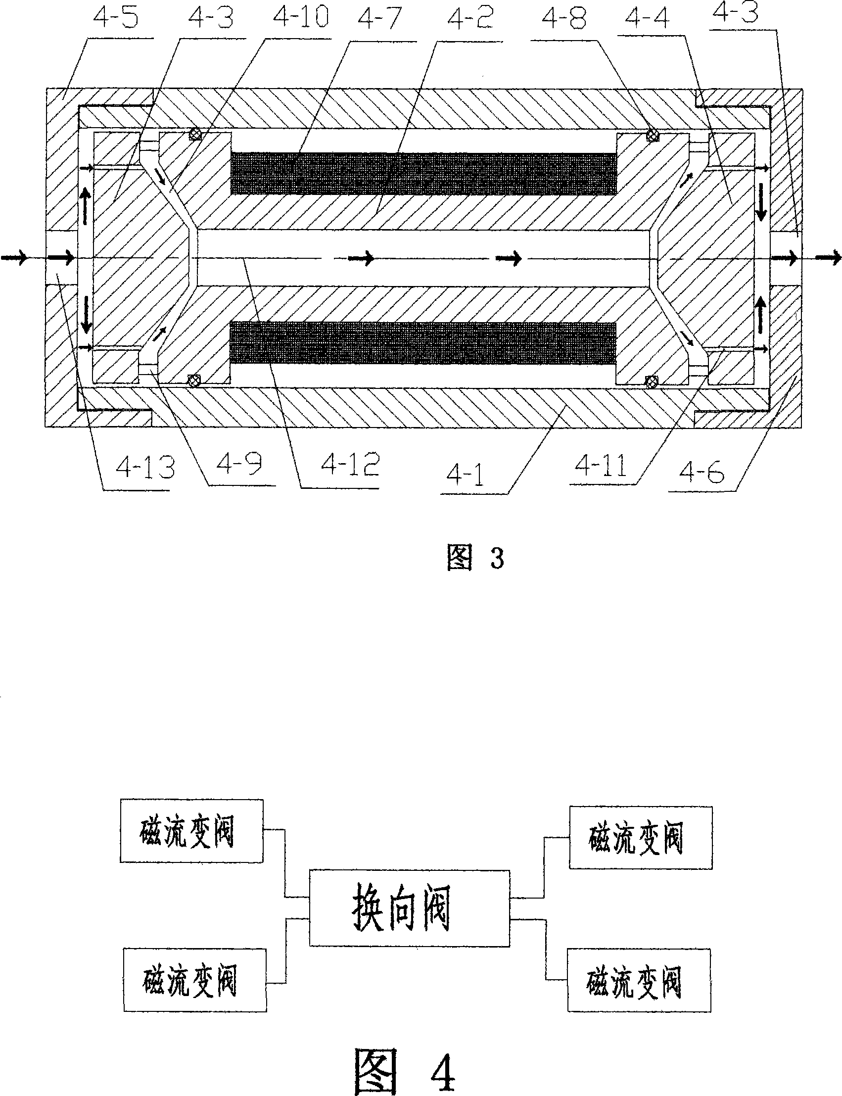
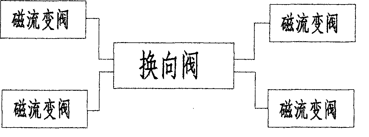
[0021] Referring to the accompanying drawings, the magneto-rheological electro-hydraulic control reversing valve for hydraulic support includes: reversing valve body 5, reversing valve left end cover 1, reversing valve right end cover 2, reversing inner valve core 3, reversing outer The spool 6 and the reversing valve working liquid port 7, the liquid inlet port 8 and the reversing valve return port 9, the reversing outer spool 6 is fixedly installed in the reversing valve body 5, and the reversing inner spool 3 is sealed and contacted. Set in the reversing outer valve core 6, the reversing valve working liquid port 7, the liquid inlet port 8 and the reversing valve return port 9 are moved by the reversing inner valve core 3 through the inner cavity of the reversing inner valve core 3 To realize the reversing, the left end cover 1 of the reversing valve and the right end cover 2 of the reversing valve are fixed to both ends of the reversing valve body 5, and the left end cover ...


PUM


Abstract

A magneto-rheological electro-hydraulic transformation directional control valve used for a hydraulic supporter uses realizes the control of a hydraulic directional valve by utilizing the characteristics of the magneto-rheological transformation fluid, overcomes the defects of larger output fluctuation caused by frequent tuning on-off and reversing impact of the traditional hydraulic valve and improves the stability of a hydraulic system. The directional control valve adopts the schemes that the valve is provided with a reversing valve body, a left end cover of the reserving valve, a right end cover of the reserving valve, an inner reversing valve core, an outer reversing valve core and a working liquid opening of the reversing valve. The liquid inlet and outlet which are arranged on the left and right end covers of the reversing valve and are used for controlling the inner reversing valve core to move are respectively provided with a magneto-rheological transformation fluid valve. The hydraulic supporter has the beneficial effect of pushing a main reversing valve to carry out reversing of the working liquid of the traditional hydraulic system by utilizing the magneto-rheological fluid. The whole reversing valve needs not to carry out fine filtering on the liquid and has simple manufacturing technique. The hydraulic supporter is suitable for batch production and has low cost.

Description

Technical field [0001] The invention relates to a magneto-rheological electro-hydraulic control reversing valve, in particular to a magneto-rheological electro-hydraulic control reversing valve for a hydraulic support used in a fully mechanized coal mining face hydraulic support computer automatic control system. Background technique [0002] With the continuous development of science and technology, especially the development of high-tech represented by electronic technology and information technology, the hydraulic control system is also developing in the direction of miniaturization, intelligence and economy. As the core component of the hydraulic control system, the traditional hydraulic valve has problems such as moving mechanical parts, complex structure, high processing requirements, easy wear, and high cost. Moreover, the oil in these servo valves has to flow through many small gaps, which are harmful to the oil. The dirt in the liquid is very sensitive, and it is ea...

Claims


Application Information

Patent Timeline
Patent Type & Authority Patents(China)
IPC IPC(8): E21D15/51E21D23/16
Inventor 赵灿刘丹丹汤春瑞
Owner 黑龙江科大科技开发有限公司
Learn More