
Steel cold bending test machine

A technology of cold bending test and steel, which is applied in the direction of applying stable bending force to test the strength of materials, etc. It can solve the problems of complicated installation process, difficulty in placing steel, threat to personal safety of test operators, etc., and achieve high test accuracy.

Active Publication Date: 2008-08-13
北京城建建设工程有限公司
View PDF0 Cites 7 Cited by
  • Summary
  • Abstract
  • Description
  • Claims
  • Application Information

AI Technical Summary

Problems solved by technology

[0003] The hydraulic cylinder of the universal testing machine is set vertically, which is divided into two types: upper type and lower type. Although it is relatively low, the workbench is too large, and it is very inconvenient to take and place samples
During the bending test, the distance between the backup rolls is adjusted manually, and the distance is measured with a steel ruler. When adjusting the backup rolls, it is necessary to fix the support with a wrench, which is labor-intensive. If errors occur during the adjustment of the backup rolls , the bending degree required by the specification will not be reached, which will affect the cold bending test results
Different diameters of steel need to use punches of different sizes. The support of the universal testing machine is heavy, the installation process is complicated, and it is difficult to replace the punch. Low
[0004] The body of the universal testing machine is large, and it is difficult to place the steel, and the position of the steel cannot be fixed, and it is easy to move or fly out during the bending process, posing a threat to the personal safety of the test operator and posing a safety hazard

Method used


Image

  • Steel cold bending test machine
  • Steel cold bending test machine
  • Steel cold bending test machine

Examples


Embodiment Construction

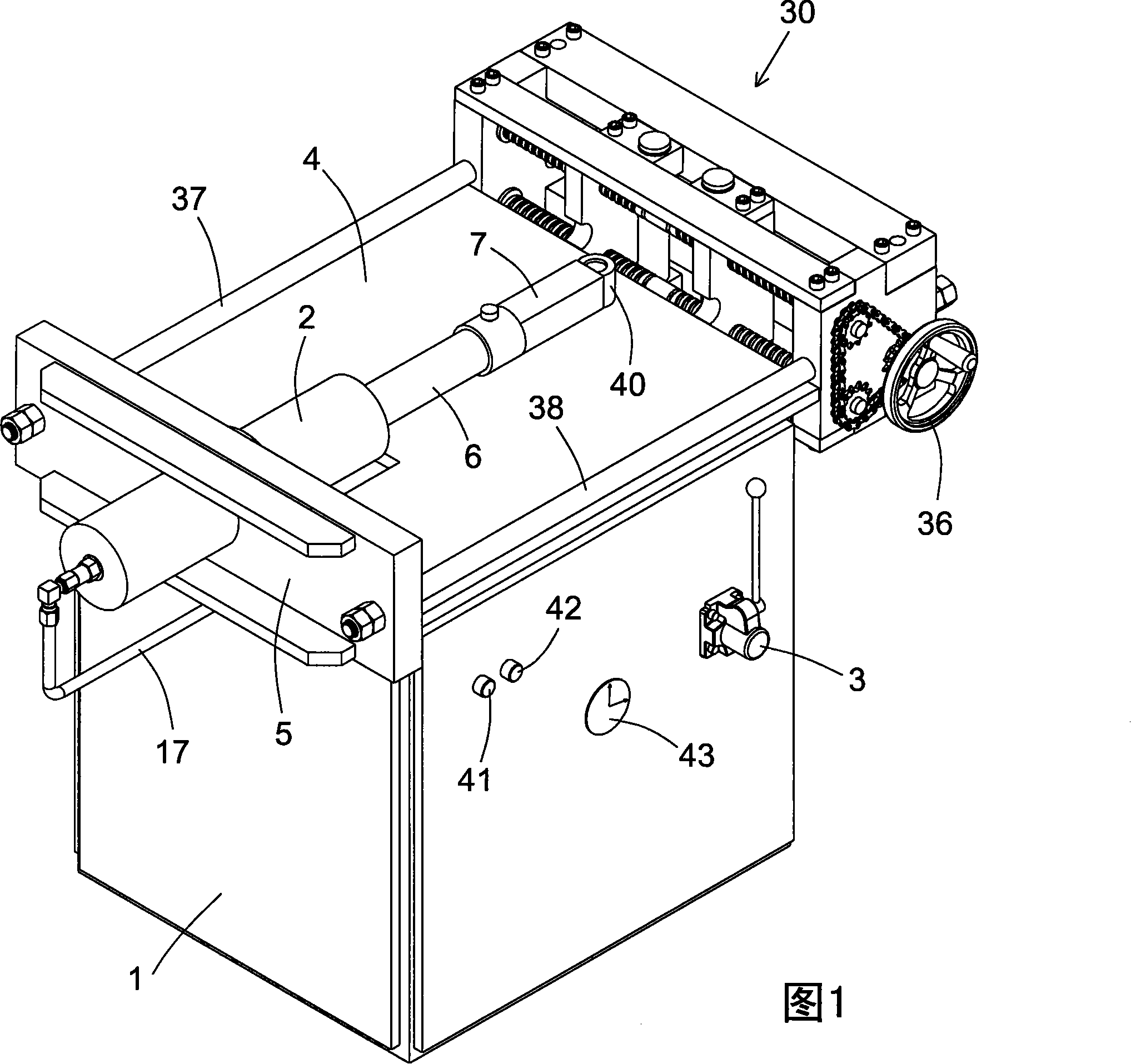
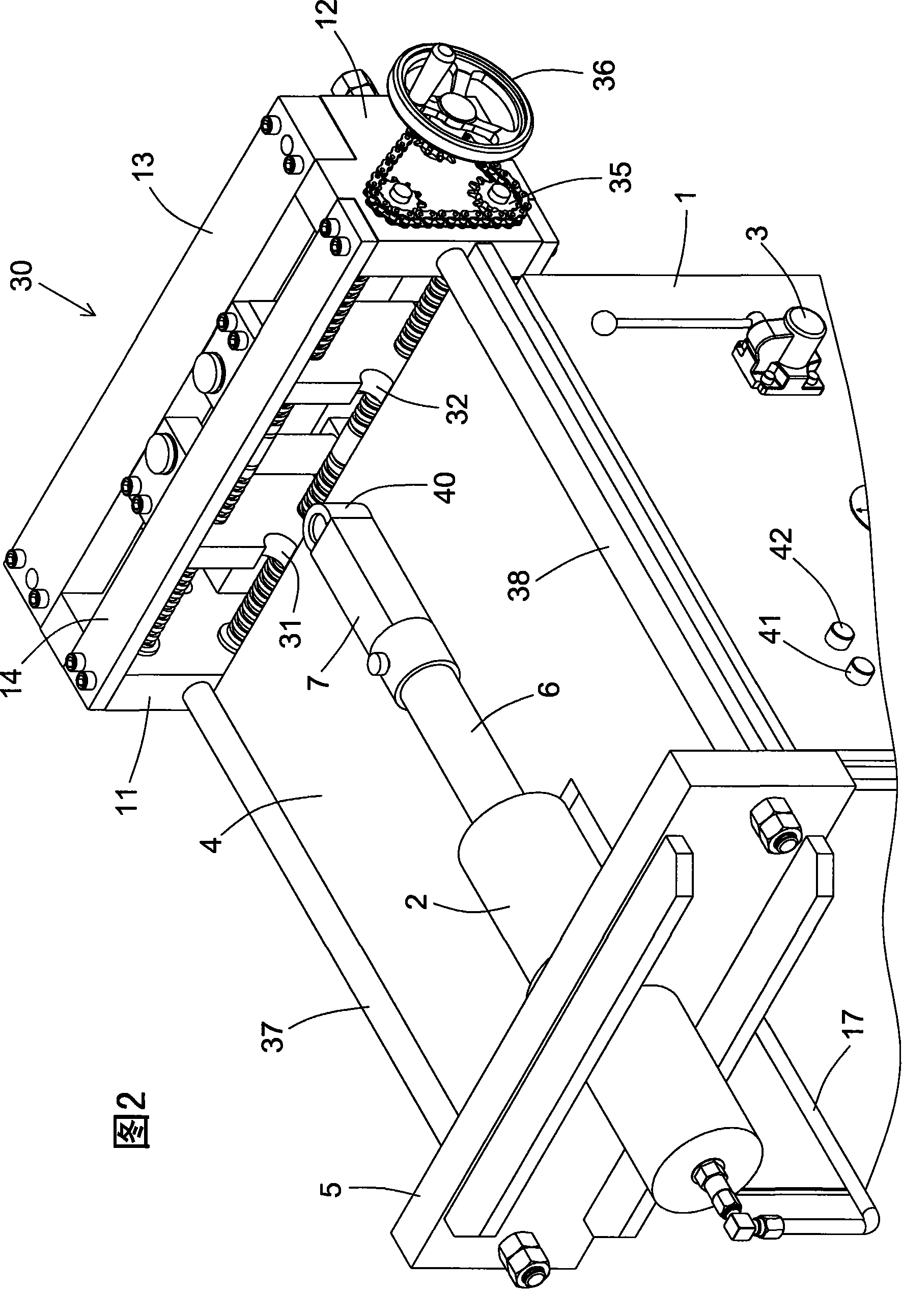
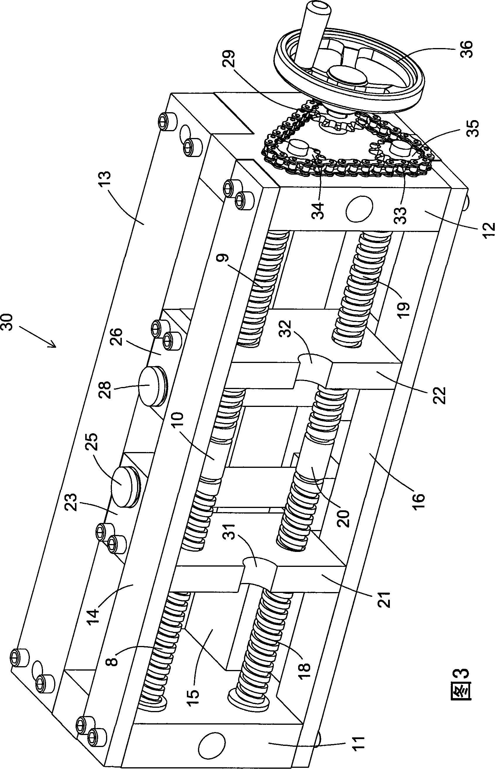
[0019] Label in the figure

[0020] 1 Chassis 2 Hydraulic Cylinder 3 Manual Reversing Valve 4 Workbench

[0021] 5 support plate 6 piston rod 7 ejector rod 8 upper left screw

[0022] 9 Upper right screw 10 Upper lead screw 11 Left side plate 12 Right side plate

[0023] 13 Front cover 14 Rear cover 15 Front base 16 Rear base

[0024] 17 Oil pipe 18 Bottom left screw 19 Bottom right screw 20 Bottom lead screw

[0025] 21 left slider 22 right slider 23 left pressure plate 24 left supporting plate

[0026] 25 left column 26 right platen 27 right supporting plate 28 right column

[0027] 29 drive sprocket 30 adjustment bracket 31 groove 32 groove

[0028] 33 chain 34 upper right sprocket 35 lower right sprocket 36 handwheel

[0029] 37 left pull rod 38 right pull rod 39 steel 40 punch

[0030] 41 Push button switch 42 Push button switch 43 Pressure gauge

[0031] Please refer to Fig. 1, Fig. 2, Fig. 3, Fig. 4, the present invention is a kind of steel cold bending testing ...


PUM


Abstract

A rolled steel cool-deforming test machine, comprising a case, a hydraulic pressure system which is composed of a hydraulic pressure cylinder, an oil pump, an oil tank, a handle reversing valve. A work table is set at top of the case. A supporting plate is set on rear end of the work table. A regulating bracket is set on front end. The hydraulic pressure cylinder is embedded in middle of the supporting plate. A mandril is connected to a piston rod of the hydraulic pressure cylinder. A punch is connected to front end of the mandril. The regulating bracket is composed of a left plate, a right plate, a front plate, a rear plate, a front bottom plate and a rear bottom plate. A right sliding block and a left sliding block are set between the left and right plates. The left and right sliding blocks are spiro-connected to an upper right chain wheel and a lower right chain wheel via a screw. A right vertical column is connected to front end of the left sliding block; a right vertical column is connected to front end of the right sliding block; ends of the upper and lower screw rods extend from the right plate, connected to the upper right chain wheel and lower right chain wheel. A handle wheel is set outside of the right plate, connected to the driving chain wheel which is connected to the upper right and lower right chain wheels via chains. The product is convenient to operate, save and reliable with high test precision, which is applied to bending test detection of various rolled steels.

Description

technical field [0001] The invention relates to a steel material bending test detection instrument and equipment. Background technique [0002] At present, steel bending detection is done by universal testing machine. [0003] The hydraulic cylinder of the universal testing machine is set vertically, which can be divided into two types: the upper type and the lower type. Although it is relatively low, the workbench is too large and it is inconvenient to take and place samples. During the bending test, the distance between the backup rolls is adjusted manually, and the distance is measured with a steel ruler. When adjusting the backup rolls, it is necessary to fix the support with a wrench, which is labor-intensive. If errors occur during the adjustment of the backup rolls , the bending degree required by the specification cannot be reached, which will affect the cold bending test results. Different diameters of steel need to use punches of different sizes. The support of ...

Claims


Application Information

Patent Timeline
Patent Type & Authority Applications(China)
IPC IPC(8): G01N3/20
Inventor 孙永泉罗金海孙建云
Owner 北京城建建设工程有限公司
Learn More