
Formaldehyde oxidation reactor

An oxidation reactor and oxidizer technology, applied in chemical/physical/physical chemistry fixed reactor, oxidation to prepare carbonyl compounds, organic chemistry, etc., can solve the problem of unutilized process waste heat, reduced heat exchange efficiency, waste of heat energy, etc. To overcome the stress cracking phenomenon, solve the problem of stress corrosion, and improve the exchange efficiency

Inactive Publication Date: 2011-03-23
EVERFIRST WISEFUND TECH BEIJING
View PDF0 Cites 0 Cited by
  • Summary
  • Abstract
  • Description
  • Claims
  • Application Information

AI Technical Summary

Problems solved by technology

The two-stage oxidation reactor is composed of upper and lower parts. The upper part is the reaction part. When the ternary mixed gas of methanol, air and water vapor enters the catalyst layer ignited and heated by the electric furnace, it will undergo oxidation reaction to generate formaldehyde gas; the lower part is In the cooling section, the high-temperature formaldehyde gas generated by the reaction is cooled and sent out by the cooling water, and the cooling water is discharged under normal pressure. Although the purpose of cooling is achieved, the waste heat of the process is not utilized, wasting a lot of heat energy and consuming a lot of energy. Cooling water
This structure makes only the chamfered part of the pure copper rod 110 contact with the inner wall of the heat exchange tube 104, so that the formaldehyde gas can circulate, thus reducing the heat exchange efficiency and increasing the gas flow resistance, and the solid copper rod also increases the cost
[0009] In addition, because the oxidation chamber 112 that generates formaldehyde gas is provided with components such as the quaternary mixed gas inlet 108, the catalyst layer 107 must be kept away from the top cover. Therefore, when replacing the catalyst, the head must be removed first, and then the operator passes through the ladder. Enter the oxidation chamber to pave the catalyst, which makes it very inconvenient to replace the catalyst

Method used


Image

  • Formaldehyde oxidation reactor
  • Formaldehyde oxidation reactor
  • Formaldehyde oxidation reactor

Examples


Embodiment Construction

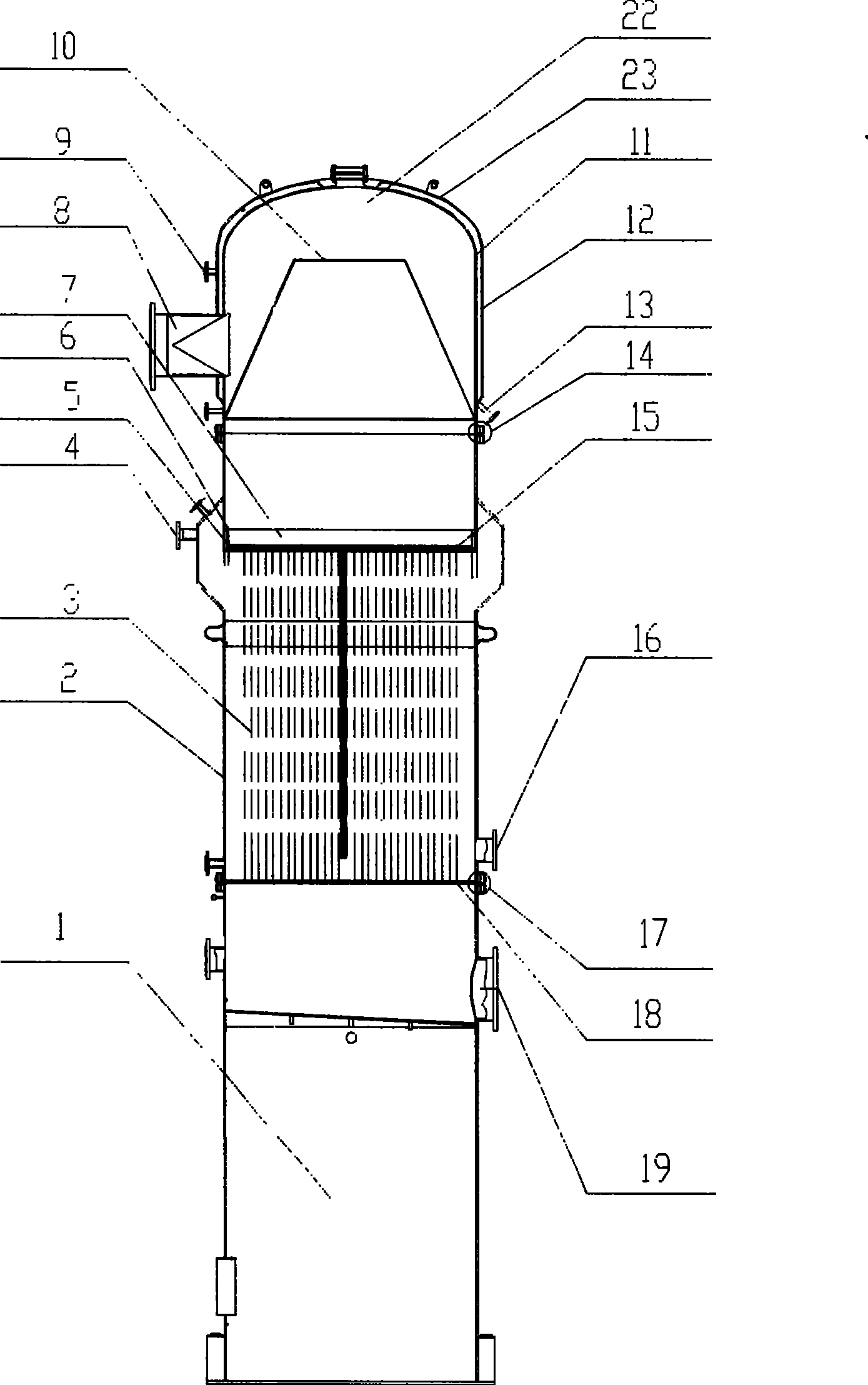
[0062] see first figure 1 The schematic diagram of the shown formaldehyde oxidation reactor of the present invention, the formaldehyde oxidation reactor of the present invention comprises:

[0063] top cover 22;

[0064] The oxidizer main cylinder 2 connected to the top cover 22 is provided with a catalyst layer 7 for oxidative dehydrogenation reaction to generate formaldehyde gas;

[0065] A device connected to the main cylinder body 2 of the oxidizer to output the generated formaldehyde gas, in this case, the device is a skirt 1 provided with a formaldehyde gas outlet 19;

[0066] It is characterized in that the top cover 22 includes:

[0067] The thermal insulation jacket 12 is composed of an inner cylinder 11 and an outer cylinder 23 that are sealed and connected, and a heating interlayer is formed between the outer cylinder 23 and the inner cylinder 11;

[0068] Enter the quaternary mixed gas inlet 8 inside the top cover 22 from the outer cylinder 23 and the inner cyl...


PUM


Abstract

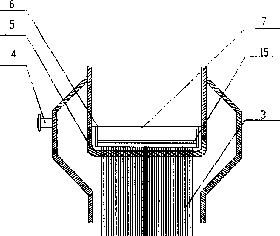
The invention discloses a formaldehyde oxidation reactor comprising: a cover; an oxidation device main barrel connected with the cover, in which a catalyst layer for performing oxidation dehydrogenation rection and generating formaldehyde gas is arranged; and a device connected with the oxidation device main barrel to output the generated formaldehyde gas. The reactor is characterized in that theoxidation device main barrel is provided with a steam outlet on the upper end of the oxidation device main barrel; an upper pipe plate under the steam outlet, wherein the upper end of the upper pipe plate is fixed on the oxidation device main barrel; in the main barrel, the upper pipe plate is a sub-flat pipe plate with radian, the two ends are tip-tilted to form upper ends, the upper ends are connected and integrated with the inner wall of the oxidation device main barrel by welding. Because the upper pipe plate is the sub-flat pipe plate with radian, the upper pipe plate has sufficient elongating space, the stress craze phenomena due to high difference in temperature is overcame, and stress corrosion problem in the oxidation device residual-heat boiler segment is solved.

Description

technical field [0001] The invention relates to a formaldehyde oxidation reactor, in particular to a formaldehyde oxidation reactor which can eliminate the stress cracking state of the upper tube plate due to the existence of high temperature difference. Background technique [0002] The formaldehyde oxidation reactor is the key equipment for formaldehyde production, its quality will be directly related to the quality of the product and affect the improvement of economic benefits. The main function of the oxidizer is to oxidize and dehydrogenate methanol to generate formaldehyde gas, recover the heat of the reaction gas and cool the reaction gas. [0003] At present, domestic formaldehyde reactors mainly have two-stage and three-stage structures. The two-stage oxidation reactor is composed of upper and lower parts. The upper part is the reaction part. When the ternary mixed gas of methanol, air and water vapor enters the catalyst layer ignited and heated by the electric fur...

Claims


Application Information

Patent Timeline
Patent Type & Authority Patents(China)
IPC IPC(8): C07C47/052C07C45/29B01J19/24
Inventor 雷得定唐家源郝丙业
Owner EVERFIRST WISEFUND TECH BEIJING
Learn More