
Omnidirectional moving spherical robot

A spherical robot and motion technology, applied in manipulators, motor vehicles, automatic toys, etc., can solve the problems of difficulty in charging and maintenance, increased control difficulty, and low practicability, so as to improve water surface walking ability and impact resistance , Conducive to centralized and unified control, fast system response

Inactive Publication Date: 2008-07-30
NANJING CARVEDGE TECH
View PDF3 Cites 28 Cited by
  • Summary
  • Abstract
  • Description
  • Claims
  • Application Information

AI Technical Summary

Problems solved by technology

The structure of this scheme is relatively complex, the center of gravity is high, it cannot be turned at any point in situ, it is difficult to carry accessories outside, and there are difficulties in charging and maintenance.
[0006] Generally speaking, the existing spherical robot solutions have their own advantages and disadvantages, but most of them have the disadvantages of complex structure, difficult engineering realization and low practicability
In particular, the steering motion of some devices is coupled with the forward motion, which makes the state of the driving mechanism inside the sphere uncertain and increases the difficulty of control; it is rarely possible to turn in situ at any point, which limits the use of the robot in narrow and tortuous spaces , and there is no in-situ steering method of the spherical shell relative to the ground; there is no external fixed interface or accessories cannot be mounted outside the spherical shell, resulting in difficulties in debugging, charging and maintenance in actual use, and at the same time limiting the effective use of various environmental detection sensors and manipulators use

Method used


Image

  • Omnidirectional moving spherical robot
  • Omnidirectional moving spherical robot
  • Omnidirectional moving spherical robot

Examples


Embodiment Construction

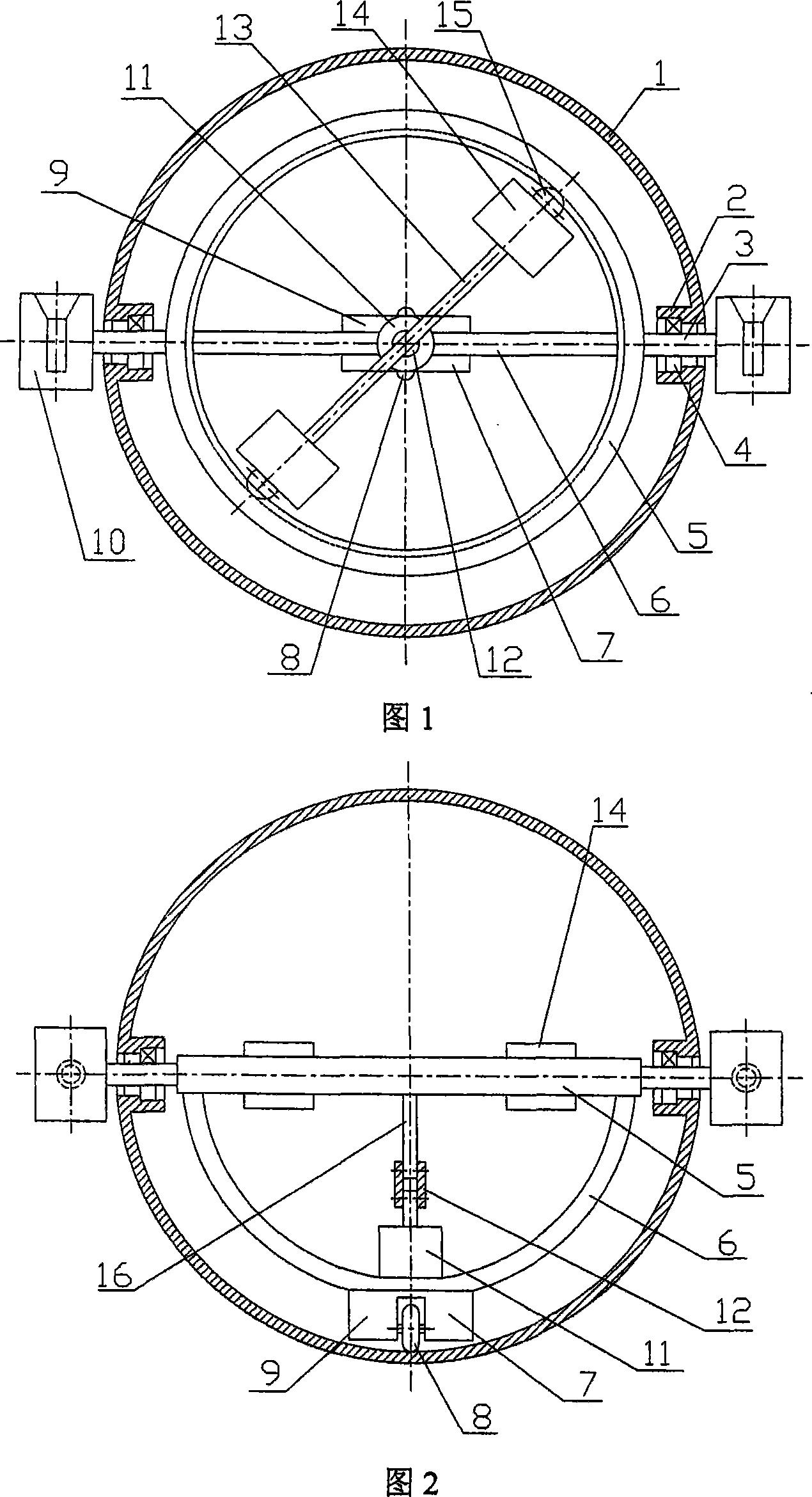
[0024] As shown in Fig. 1 and Fig. 2, Embodiment 1 of the present invention is: a spherical robot with omnidirectional motion, which is composed of a spherical shell 1 and an internal walking drive device. Its walking driving device includes a horizontal ring 5 and a semicircular frame 6 vertically fixed on the lower side of the horizontal ring 5; the horizontal ring 5 is symmetrically fixed to a pair of short shafts 3 along the outer side of the horizontal ring 5, and the short shaft 3 is along the diameter direction of the sphere. The bearing 4 and the spherical shell 1 form a revolving pair; the bottom of the semicircular frame 6 is fixedly connected with a linear traveling mechanism, which is composed of a traveling motor 7, a main wheel 8 and a counterweight 9, and the main wheel 8 is driven by the traveling motor 7 along the ball. The inner side of the shell 1 rolls, and the center of gravity of the sphere is moved forward and backward to push the sphere to move in a stra...


PUM


Abstract

The invention discloses a spherical robot of omnidirectional movement, which relates to the technical field of spherical robot. A walking driving device comprises a horizontal circle (5) and a semicircle frame (6) vertically and fixedly connected with a lower side of the horizontal circle, wherein, the horizontal circle forms a revolute joint with a sphere shell via a minor axle (3) and a bearing; a bottom of the semicircle frame is fixedly connected with a straight line walking device comprising a walking motor (7), a main wheel (8) and a counterweight; the main wheel is driven by the walking motor and rolls along an inner side of the sphere shell so as to push the sphere to move along a straight line by shuttling the sphere gravity; a top of the semicircle frame is provided with a steering control mechanism comprising a direction change motor (11), a horizontal rod (13) and a mass block (14); the horizontal rod and the mass block rotate around a geometric center line of the semicircle frame under the driving force of the steering motor, thus causing the sphere to rotate in an opposite direction and changing the moving direction of the sphere. The invention has the advantages of novel structure, simple control and good stability; besides, and has the ability of omnidirectional movement, pivot steering and accessory parts carrying.

Description

technical field [0001] The invention relates to a spherical robot with omnidirectional movement, which belongs to the technical field of mechatronics, in particular to a spherical robot, which can be used in the fields of environment detection, military investigation, alien exploration, family entertainment and the like. Background technique [0002] Spherical robot is a new type of rolling walking robot, which has the characteristics of fast movement speed, good off-road performance, and relatively simple control. It has gradually become one of the hotspots in the field of intelligent robot research at home and abroad. The first real spherical robot was designed by Halme et al. in Finland in 1996 (see "Motion Control of A Spherical Mobile robot", Proceedings of AMC'96-MIE, IEEE, 1996: 259-264), they are in the spherical shell A drive wheel is set up, which is driven by a motor to roll in the spherical shell, and the linear motion of the robot can be realized by changing the...

Claims


Application Information

Patent Timeline
IPC IPC(8): B62K1/00B25J5/00A63H11/00B60B19/00
Inventor 杨忠姜斌吴惠祥王志胜董荣俊吴涛
Owner NANJING CARVEDGE TECH
Learn More