Method of manufacturing bit tool used for cutting plastic film particle

A production method and plastic film technology, which is applied in the field of toothed cutter processing, can solve the problems of easy wire breakage, uneven cutting particles, and joint marks, etc., so as to achieve a dense and sharp metal structure on the tooth surface, and Precise layout and low production cost

Inactive Publication Date: 2008-07-30
杜宁
View PDF1 Cites 4 Cited by
  • Summary
  • Abstract
  • Description
  • Claims
  • Application Information

AI Technical Summary

Problems solved by technology

At present, there are two main methods of making this kind of tool teeth: 1. Grinding method, which grinds the heat-treated metal block blank with a high-precision grinding head. The metal block used in this method must be The blank after heat treatment, otherwise a large number of burrs will be generated due to the insufficient hardness of the metal during the grinding process, and it is difficult to erase the high finish. The burrs will affect the cutting quality and service life of the tool teeth. Grinding wheels are usually used. Due to the serious friction between the grinding wheel and the heat-treated metal block, the accuracy of the grinding wheel changes rapidly. Because the tool teeth require high precision, it is necessary to replace the grinding wheel. After replacing the grinding wheel, it is difficult to find out where the grinding wheel is. 2. Cutting method: use cutting machine to cut the above-mentioned cutter teeth, which has high requirements on equipment, because CNC machine tools are usually difficult to To process the above-mentioned cutters, the cutter teeth of such cutters are cut by slow-moving wire-cutting machine tools. The wires are easy to break during the cutting process. When cutting with a thicker wire, the corner of the bottom of the tooth may become an arc corner because the diameter of the wire is too large, so that the tool moves unevenly when cutting the particle and eventually causes the deformation of the particle, such as cutting hexagonal particles. There are two corners are rounded and other disadvantages

Method used


Image

  • Method of manufacturing bit tool used for cutting plastic film particle
  • Method of manufacturing bit tool used for cutting plastic film particle
  • Method of manufacturing bit tool used for cutting plastic film particle

Examples


Embodiment

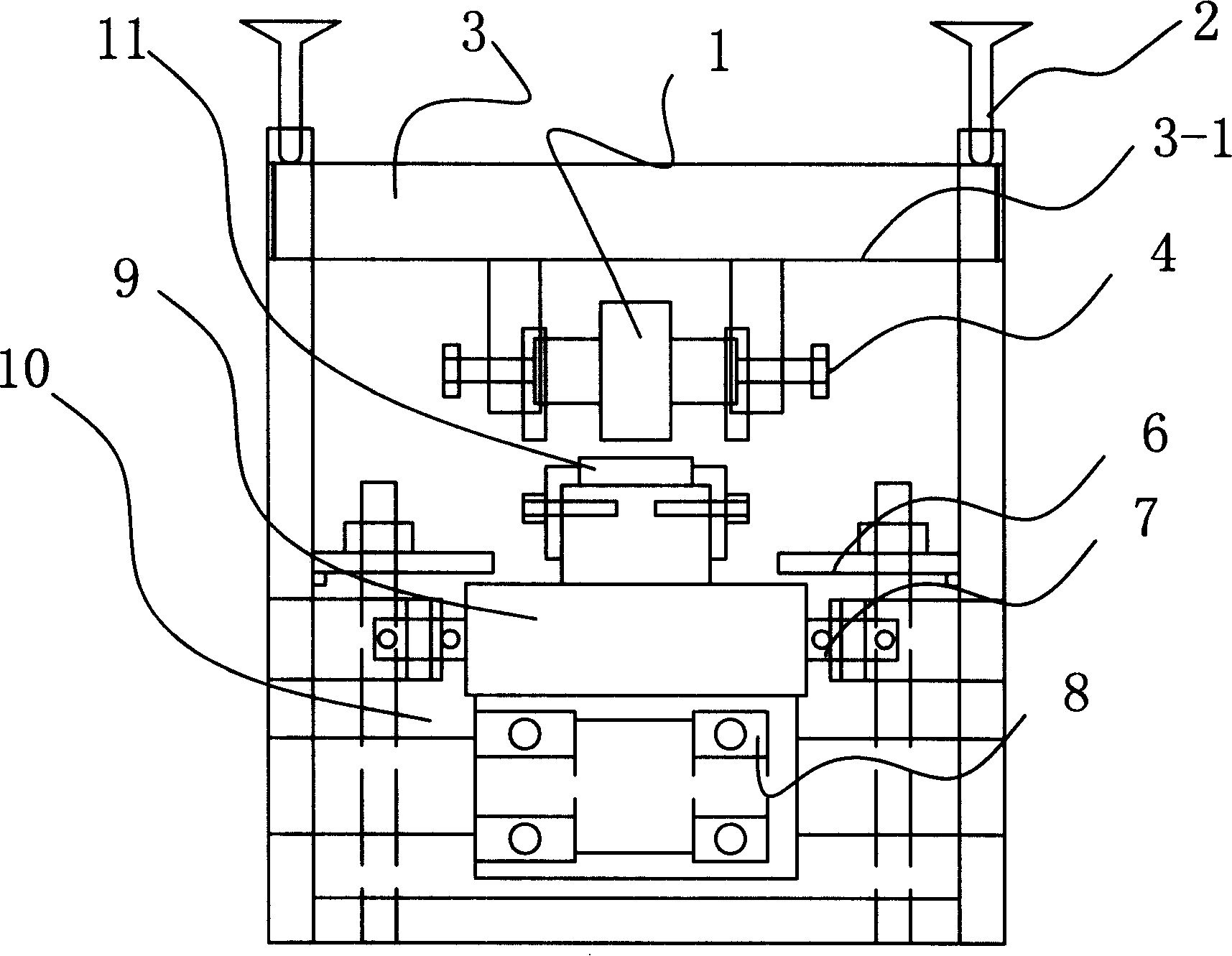
[0026] Example: such as figure 1 , 2, 3, 4, 5, 6, 7, the manufacturing device of the cutter shown, it comprises upper frame 3, underframe 10, is used to support the formwork 10 of metal block, is located on upper frame 3 and can rotate along the axis The outer surface of the rolling cylinder 1 with the required tooth shape, the mold frame 9 locks the metal block 11, the rolling cylinder 1 and the mold frame 9 are opposite up and down, and the mold frame 9 is connected with a translational mechanism Motor (not marked on the picture). The upper frame 3 has a beam 3-1, the rolling cylinder 1 is fixed under the beam 3-1, the two sides of the beam 3-1 are movable on the upper frame through the screw rod 2, and the adjusting screw rod 2 can be adjusted up and down The height of the rolling cylinder adjusts the distance between the rolling cylinder and the metal block, and the rolling cylinder 3 can rotate. The left and right sides of the formwork 9 are provided with limit bearings...


PUM


Abstract

The invention relates to a method for processing a cutter, in particular to a method for manufacturing a cutter used for cutting plastic film particles. The method comprises the following steps: a rolling cylinder is made; a required tooth form is manufactured on the outer surface of the rolling cylinder and the hardness of the tooth form on the rolling cylinder is more than HRC60; a metal block with the HRC less than 25 is placed on a mould rack and the obtained rolling cylinder is used for rolling cutter teeth on the surface of the metal block; the obtained cutter is then treated thermally to ensure that the HRC of the cutter is more than 60. The invention is characterized in that: the obtained cutter has high hardness, precise arrangement of the cutter teeth, compact and sharp metal structure on the cutter tooth face, smooth cutter tooth face, no joint traces on the cutter, short production cycle of the cutter, wide material sources, low production cost and the invention is also characterized in that tools used in cutter production has long service life and the cutter is unlikely to catch the film particles during cutting; the particles manufactured by the obtained cutter are not inclined to be deformed, etc.

Description

technical field [0001] The invention relates to a processing method of a cutter, in particular to a processing method of a toothed cutter for cutting plastic film particles. Background technique [0002] The toothed cutter for cutting plastic film particles is used in conjunction with a special cutting machine to cut plastic film particles of various shapes, such as hexagonal, rectangular, rhombus, etc. flat knife. The above-mentioned plastic film particles can be used in various occasions, such as making various decorations, clothing fabrics and configuring paints and coatings for various purposes to achieve effects such as changing colors and flashing. This kind of cutter has cutter teeth, and each cutter tooth is cut separately when cutting. Usually the cutter teeth are the most difficult parts of the cutter, and the cutter has the strictest requirements on the cutter teeth. At present, there are two main methods of making this kind of tool teeth: 1. Grinding method, wh...

Claims


Application Information

Patent Timeline
Patent Type & Authority Applications(China)
IPC IPC(8): B23P15/28B23P15/40B21H7/10B21H5/00C21D9/32B26D1/00
Inventor 杜宁
Owner 杜宁
Why Eureka
Try Eureka