Eureka AIR delivers breakthrough ideas for toughest innovation challenges, trusted by R&D personnel around the world.

Bubble wet processing dust container

A dust collector, wet technology, applied in chemical instruments and methods, dispersed particle separation, use of liquid separation agents, etc., can solve the problems of complex dust collector structure, reduced filtering effect, reduced suction efficiency, etc., to prolong the stay. time, improve the filter effect, improve the effect of the filter effect

Inactive Publication Date: 2008-07-30
江门市蓬江区永兴盛五金设备有限公司
View PDF1 Cites 20 Cited by
  • Summary
  • Abstract
  • Description
  • Claims
  • Application Information

AI Technical Summary

Problems solved by technology

[0002] There are many kinds of existing dust collectors and dust collectors, including dry filter and water filter dust removal. Among them, the wet dust collector mainly uses water medium to filter. There is a Chinese patent ZL 02206663.2, the announcement date is 2003.02.26 and the name is The impact washing dust collector is familiar with this type. Its structure mainly includes a box body, a filter plate, an air extractor, an air extraction elbow, and a mesh plate. The filter plate is divided into three layers. Among them, the air extraction elbow There is a cone under the outlet end of the outlet, so that the gas is shunted to the water surface in a ring shape. This structure relies on the dust gas hitting the water surface to create water mist and generate vortices to mix the dust gas into the water for filtration, but the suctioned dust gas If it is not completely absorbed and filtered by water, the residual exhaust gas needs three layers of filtration. When a large amount of dust gas enters, the filtering effect will be reduced. Moreover, the structure of this dust collector is complicated, and the three layers of filtration will reduce the suction efficiency and consume a lot of electric energy.

Method used


Image

  • Bubble wet processing dust container
  • Bubble wet processing dust container
  • Bubble wet processing dust container

Examples


Embodiment Construction

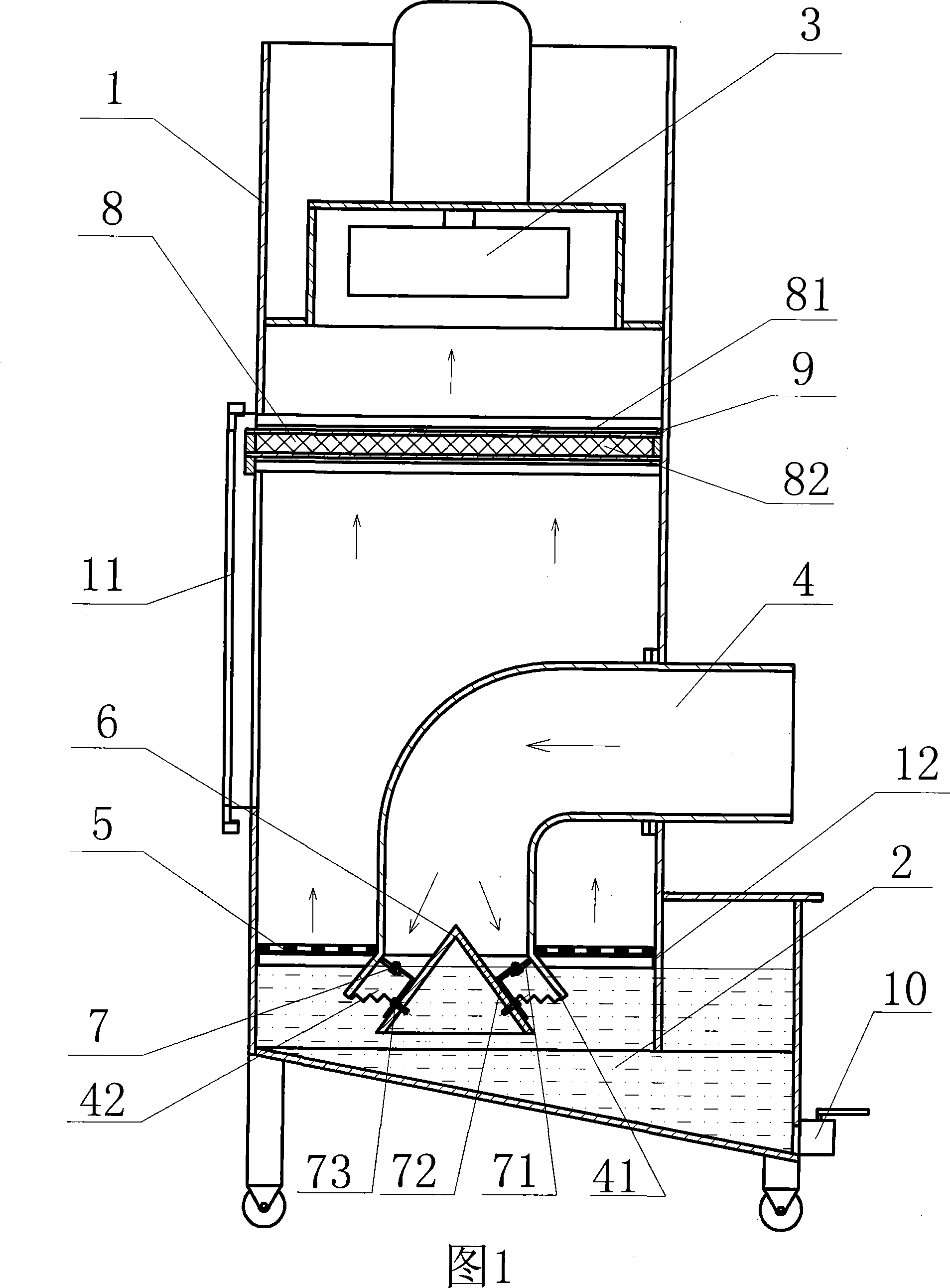
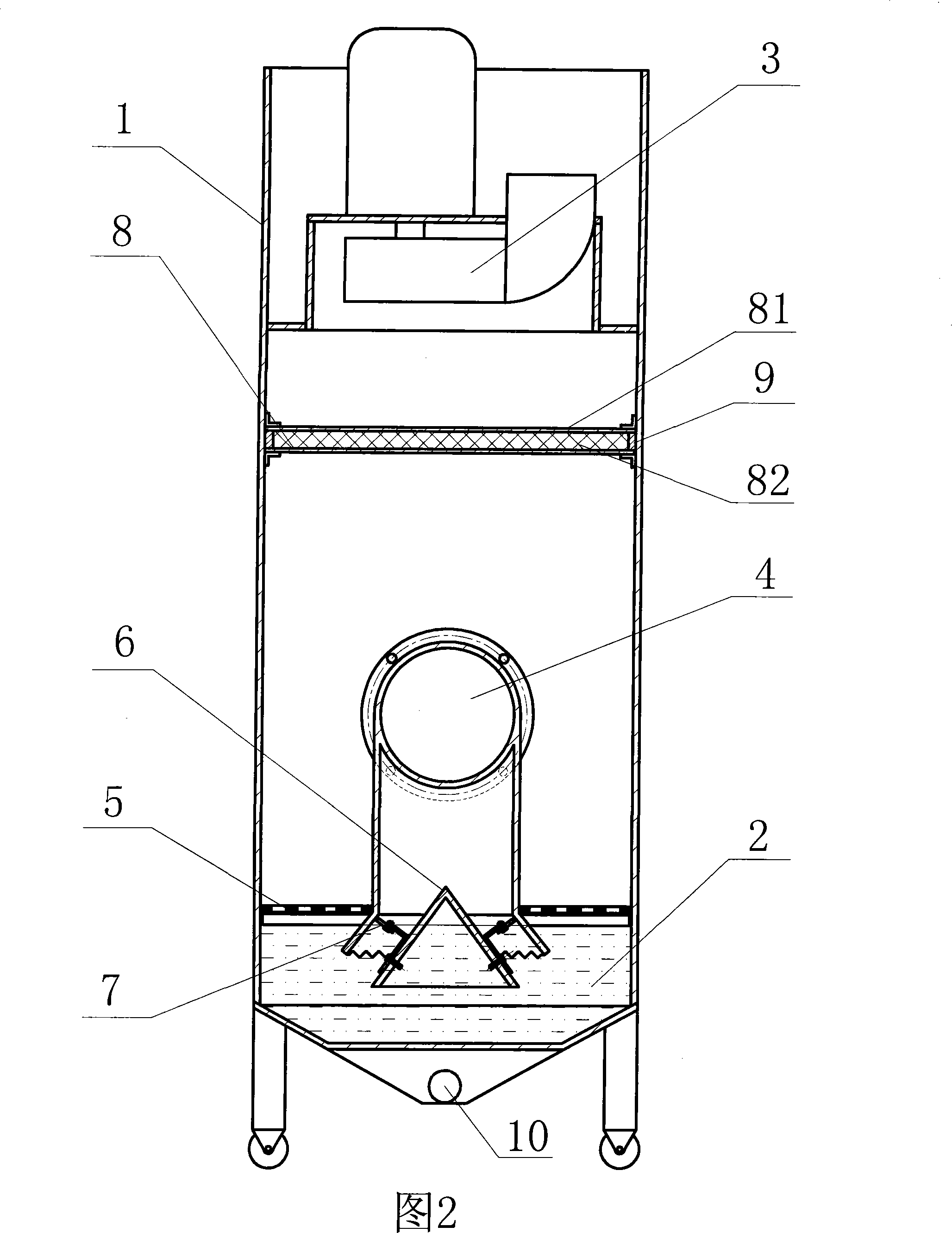
[0025] The bubble wet dust collector of the present invention will be described in more detail below in conjunction with the accompanying drawings.

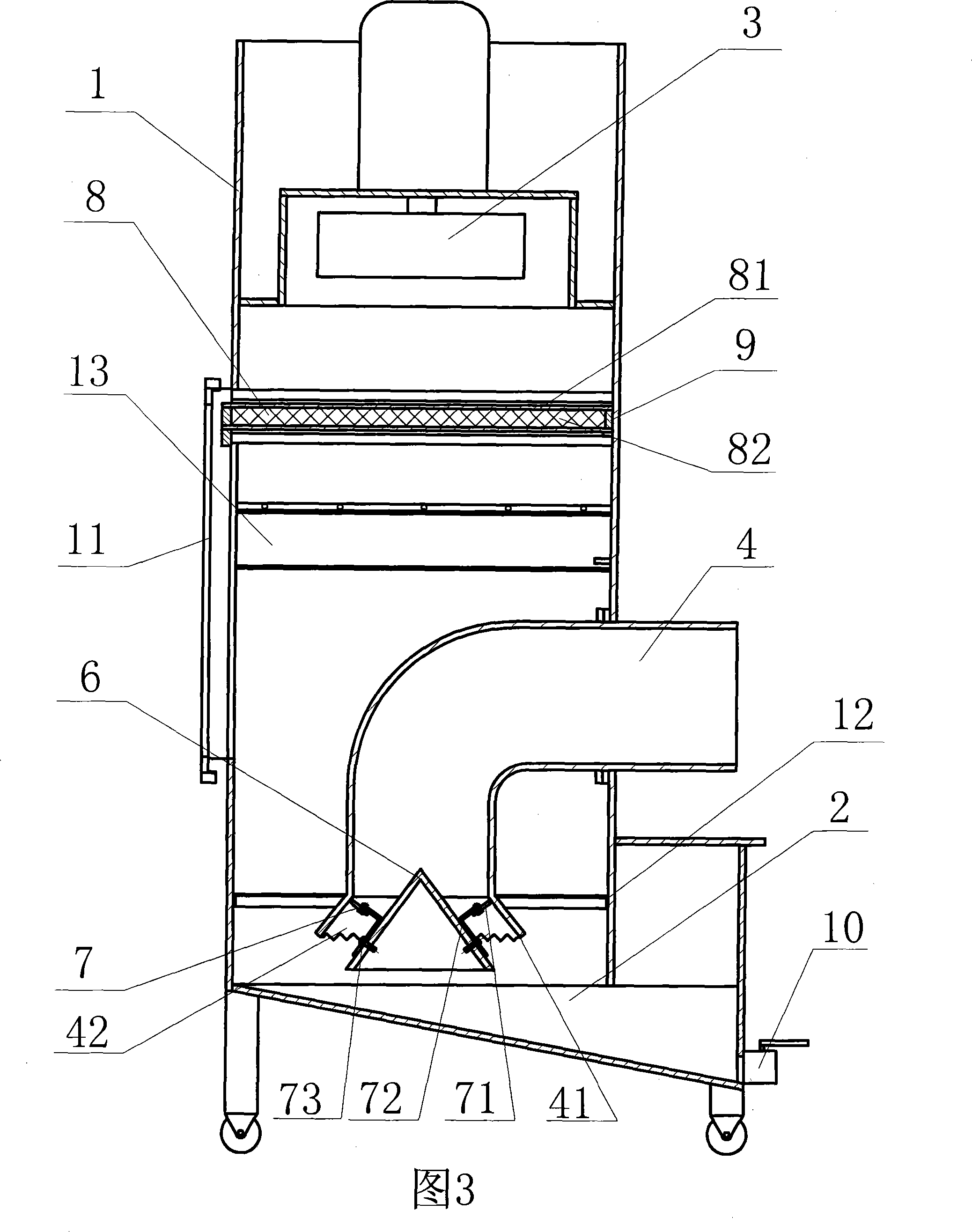
[0026] As shown in Figures 1-2, the bubble wet dust collector of the present invention includes a box body 1, a water tank 2 arranged below the box body, and an air extractor 3 installed above the box body, and an air extraction bend is introduced at the upper position of the water tank 2. pipe 4, and fixed on the box body 1, a drain pipe 10 is installed under the water tank 2, and a door 11 is provided on the side of the box body 1, and a layer of evenly distributed perforated pipes is placed at the outlet end of the suction elbow 4 The mesh plate 5 is supported by the support bar 12 arranged on the inner periphery of the box body 1, and a filter plate 8 is also arranged above the suction elbow 4 near the air inlet of the air extractor 3, and the mesh plate 5 is arranged on the In the water tank 2 close to the working water surf...


PUM


Abstract

The invention discloses a water medium filtering and dust removing bubble wet dust collector, which comprises a tank body (1), a water tank (2) arranged under the tank body (1), an ejector positioned over the tank body, a drain pipe (10) positioned below the water tank, a door (11) arranged at the side of the tank body, a filter plate (8) in the tank body, a pumping elbow (4) fixed on the water tank, a bell mouth (41) at the outlet end thereof, a layer of perforated metal sheet (5) arranged close to the working water surface and supported by a bar bearer (12) in the tank body. The bell mouth (41) enters into the water through the perforated metal sheet (5); the middle most of the lower part of the bell mouth (41) is provided with a pyramidal guide wind bucket (6) which is suspended at the inner side of the bell mouth (41) through a duct regulating thread slipping (7), thereby ensuring the outer side of the guide wind bucket (6) and the inner side of the bell mouth form an annular exhaust passage (42), size of which can be adjusted. The invention has simple structure and generates bubble through the guide wind bucket, thereby ensuring the pumped dust gas can fully enter into the water to be filtered and saving energy.

Description

technical field [0001] The bubble wet dust collector of the present invention relates to a dust collector for collecting and removing dust, in particular to a bubble wet dust collector which utilizes water to filter and remove dust. Background technique [0002] There are many kinds of existing dust collectors and dust collectors, including dry filter and water filter dust removal. Among them, the wet dust collector mainly uses water medium to filter. There is a Chinese patent ZL 02206663.2, the announcement date is 2003.02.26 and the name is The impact washing dust collector is familiar with this type. Its structure mainly includes a box body, a filter plate, an air extractor, an air extraction elbow, and a mesh plate. The filter plate is divided into three layers. Among them, the air extraction elbow There is a cone under the outlet end of the outlet, so that the gas is shunted to the water surface in a ring shape. This structure relies on the dust gas hitting the water su...

Claims


Application Information

Patent Timeline
Patent Type & Authority Applications(China)
IPC IPC(8): B01D47/02B01D50/00
Inventor 陈永杰
Owner 江门市蓬江区永兴盛五金设备有限公司
Why Eureka
Eureka Blog
Learn More