
Self-excited oscillation type high power LED constant-current driving circuit

A self-excited oscillation, constant current drive technology, applied in the direction of electric lamp circuit layout, electric light source, adjusting electric variables, etc., can solve the problems of low efficiency, uneven quality, large area of ​​linear voltage regulator, etc., to save The effect of circuit cost, life extension, and reliability improvement

Inactive Publication Date: 2008-07-23
NANTONG LIWANG MACHINE TOOL +1
View PDF0 Cites 57 Cited by
  • Summary
  • Abstract
  • Description
  • Claims
  • Application Information

AI Technical Summary

Problems solved by technology

[0005] The simplest is to connect a current-limiting resistor in series after the rectification and voltage stabilization of the mains, but this cannot achieve constant voltage and constant current drive. When the voltage fluctuates greatly, it will cause damage to the LED, and the brightness of the light will be inconsistent.
A traditional solution is to use a power frequency transformer to step down the mains power first, and then rectify and filter it into a DC voltage to drive the LED. If higher stability is required, a linear voltage regulator will be used to stabilize the voltage. ; However, the power frequency transformer is relatively heavy and occupies a large area. In addition to the low efficiency of the linear voltage regulator, it cannot meet the constant current requirements, so this method is rarely used now.
In addition, there are also ordinary switching power supplies used as drivers for high-power LEDs, but the cost of general regulated power supplies is high, the area is large, and there is no constant current control.
There is also a solution that is widely used at present, which uses a dedicated high-power LED driver chip, uses the principle of a switching converter, and supplements certain peripheral components to form a constant-voltage constant-current driver. Although the use of an integrated circuit chip can reduce the circuit area, but The price of various high-power LED driver chips is high, and the quality is uneven. The LED driver chips with internal integrated switch tubes have limited power capacity and weak load capacity. Some higher-power LEDs cannot be driven.

Method used

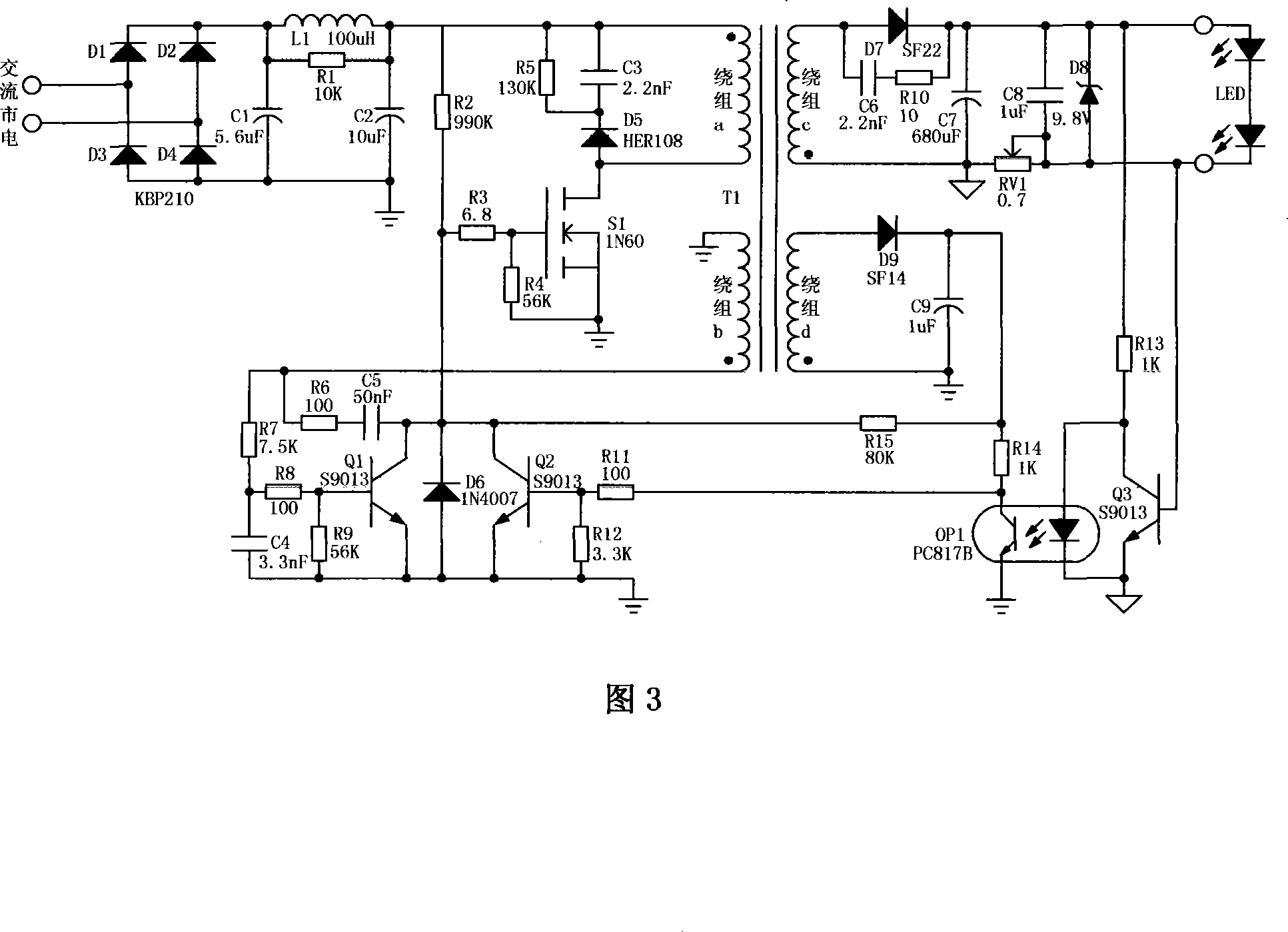

Image

  • Self-excited oscillation type high power LED constant-current driving circuit
  • Self-excited oscillation type high power LED constant-current driving circuit
  • Self-excited oscillation type high power LED constant-current driving circuit

Examples


Embodiment Construction

[0023] The purpose, circuit structure and advantages of the present invention will be further described below through specific embodiments of the present invention in conjunction with the accompanying drawings.

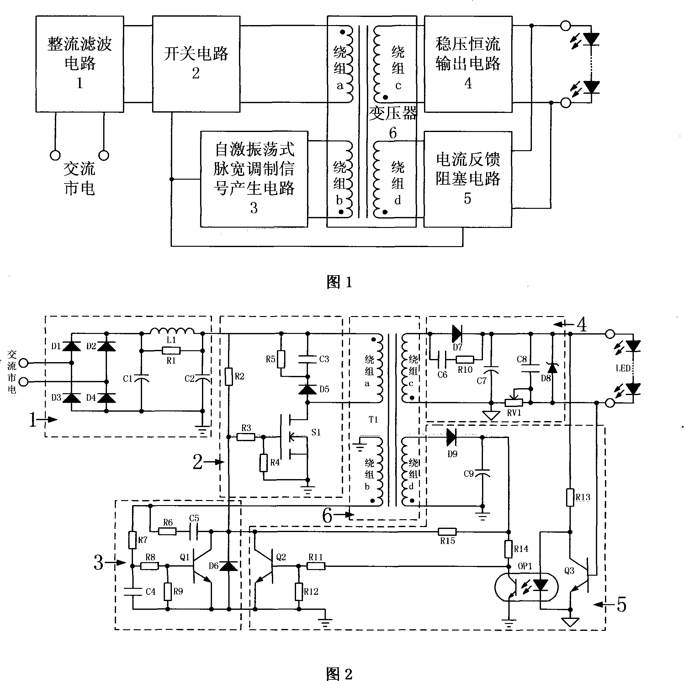
[0024] As shown in FIG. 1 , the present invention includes a rectification filter circuit 1 , a switch circuit 2 , a self-excited oscillation pulse width modulation signal generation circuit 3 , a constant voltage constant current output circuit 4 , a current feedback blocking circuit 5 and a transformer 6 .

[0025] The rectifying and filtering circuit 1 converts the AC mains power into a relatively stable high-voltage DC signal, and outputs it from the output terminal of the high-voltage DC signal to the input terminal of the high-voltage DC signal of the switch circuit 2, as the energy supply of the whole circuit; the switch circuit 2 will receive the The DC high-voltage signal is converted into a high-frequency AC signal after pulse width modulation by a high-frequ...


PUM


Abstract

The invention provides a self-oscillation type high power LED constant-current drive circuit with low cost, high reliability and stability and high drive efficiency, the circuit comprises a rectifier and filter circuit, a switching circuit, a steady voltage constant current output circuit, a transformer, a self-oscillation type pulse width modulation signals generating circuit and a current feedback obstruction circuit, wherein the rectifier and filter circuit accesses commercial power into rectification, changes the commercial power into direct current, and then outputs commercial power to the switching circuit to switch in a self-oscillation type with high frequency, then high frequency voltage of the steady voltage constant current output circuit is transformed into direct voltage through the transformer to drive the LED, simultaneously sampling current signals produces jam signals through the current feedback obstruction circuit to control the switching circuit to work, the circuit does not adopt any driving chips and only uses fewer common individual devices to form a self-oscillation type structure to drive the switching circuit and to combine current feedbacks, which realizes constant current driving of the high power LED.

Description

technical field [0001] The invention relates to a high-power LED drive circuit, in particular to a self-excited oscillation high-power LED constant current drive circuit. Background technique [0002] LED is the abbreviation of English light emitting diode (light-emitting diode), its basic structure is a piece of electroluminescent semiconductor material, placed on a shelf with leads, and then sealed with epoxy resin around it. LED has many advantages, such as long life, short start-up time, firm structure, low energy consumption, high safety in use, no ultraviolet radiation, etc. In addition, its production can achieve mercury-free, which is of great significance to environmental protection and energy saving. [0003] Due to the many advantages of LEDs compared with traditional lighting equipment, research efforts in this area have been greatly strengthened in the world, especially the research and development and production of high-power LEDs (above 1W). With the gradual ...

Claims


Application Information

Patent Timeline
Patent Type & Authority Applications(China)
IPC IPC(8): H05B37/02G05F1/46
Inventor 徐申孙伟锋李杰陆生礼时龙兴
Owner NANTONG LIWANG MACHINE TOOL
Learn More