Eureka AIR delivers breakthrough ideas for toughest innovation challenges, trusted by R&D personnel around the world.

Stirring fan component of microwave oven

A technology for microwave ovens and components, applied in the field of microwave ovens, can solve problems such as defectiveness and easy occurrence of ignition, and achieve the effect of complete matching and good wear resistance.

Inactive Publication Date: 2008-07-23
LG ELECTRONICS (TIANJIN) APPLIANCES CO LTD
View PDF0 Cites 0 Cited by
  • Summary
  • Abstract
  • Description
  • Claims
  • Application Information

AI Technical Summary

Problems solved by technology

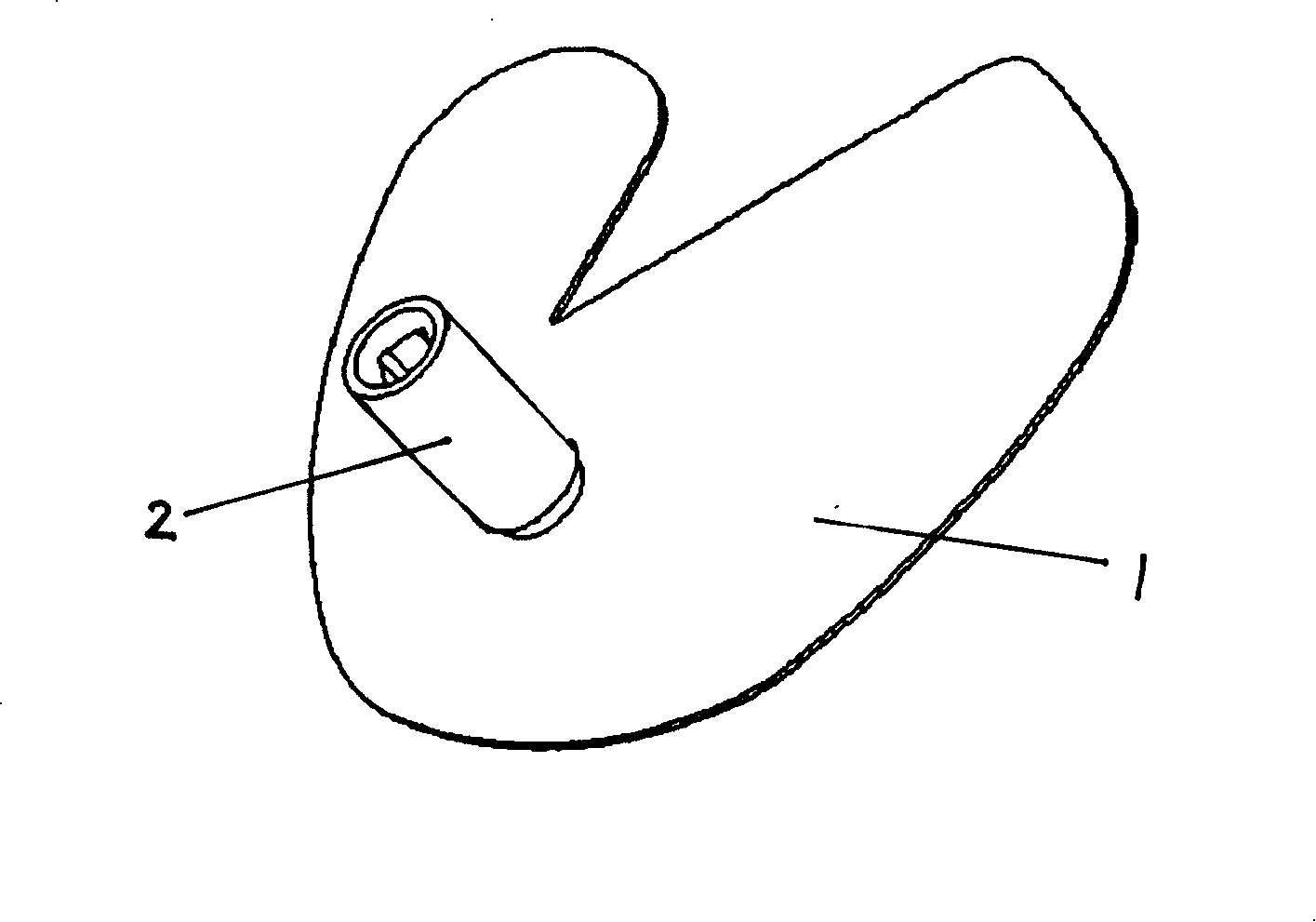
[0003] figure 1 As shown, the stirring fan assembly in the prior art is composed of the stirring fan blade 1 and the stirring fan shaft 2, and is arranged on the upper part of the furnace cavity, and the waveguide is in the microwave oven above the furnace body. Due to the use of the above-mentioned fan-shaped stirrer, the magnetron and It is very easy to spark between the waveguide covers, the spark rate is 20%, and the defect is quite serious

Method used


Image

  • Stirring fan component of microwave oven
  • Stirring fan component of microwave oven

Examples


Embodiment Construction

[0010] The stirring fan assembly of the microwave oven of the present invention will be described in detail below with reference to the accompanying drawings and specific embodiments.

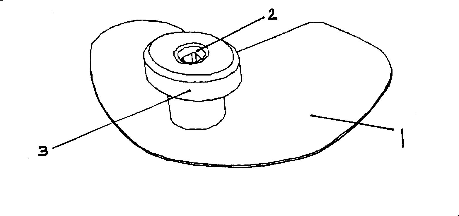
[0011] Such as figure 2 As shown, the stirring fan assembly of the microwave oven of the present invention includes a stirring fan blade 1 and a stirring fan shaft 2, and a Teflon bushing 3 (Teflon) is added to the stirring fan shaft 2 . The Teflon bushing 3 is a stepped cylinder.

[0012] Because Teflon has good wear resistance, heat resistance and microwave reflection characteristics, a Teflon ring is placed on the shaft of the stirrer, so that part of the microwave in the waveguide will be reflected by the Teflon ring when it enters the furnace body, which can be well improved. Distribution of microwaves. Make the matching between the magnetron and the furnace body intact, no sparking phenomenon, and the sparking rate is 0.

[0013] The change of shape of Fron bushing 3 is simple and eas...


PUM


Abstract

The invention discloses a stirring fan component used for microwave oven, comprising a stirring fan blade and a stirring fan shaft, a Teflon shaft bushing is stepped cylinder. The stirring component used for microwave oven has excellent abrasion-resistant, heat-resistant and microwave reflection properties, which enables the magnetron and the furnace body to match well without spark-striking phenomenon.

Description

technical field [0001] The invention relates to a microwave oven, in particular to a stirring fan assembly of the microwave oven which does not generate sparking phenomenon. Background technique [0002] In general, a microwave oven is a device that uses high-frequency (about 2450MHz per second) microwaves as a heating source to cook food through the frictional heat generated by disrupting the order of food molecules. Such microwave ovens are roughly classified into: a method in which a turntable on which food is placed is rotated in order to uniformly supply microwaves to the food in the cavity; and a system using a stirring fan to uniformly supply microwaves to the food in the cavity. Of course, the above two methods can be used at the same time. In prior art microwave ovens using stirring fan mode, stirring fan assemblies are mainly arranged in the bottom or upper part or side space of the oven cavity forming the cooking chamber. At this time, the space provided with th...

Claims


Application Information

Patent Timeline
Patent Type & Authority Applications(China)
IPC IPC(8): F24C7/02F24C15/22
Inventor 王江坤
Owner LG ELECTRONICS (TIANJIN) APPLIANCES CO LTD
Why Eureka
Eureka Blog
Learn More