
A method and the corresponding device of low bit rate service signal in optical transport network transmission

A service signal and optical transport network technology, applied in the field of optical communication, can solve problems such as inconvenient service scheduling, low bandwidth utilization, and inability to connect and download services at intermediate nodes

Inactive Publication Date: 2008-07-09
HUAWEI TECH CO LTD
View PDF0 Cites 36 Cited by
  • Summary
  • Abstract
  • Description
  • Claims
  • Application Information

AI Technical Summary

Problems solved by technology

[0017] In practical application, the above scheme has the following problems: For the OTN mapping through virtual concatenation of GFP and SDH, the circuit is complex and expensive, and end-to-end performance monitoring based on a single low-rate service signal level cannot be realized, and the intermediate node cannot be directly For up and down services, service scheduling is inconvenient; for OTN direct mapping through GFP, the bandwidth utilization rate is low, the scheduling granularity is too large, and the reliability is reduced
[0018] The main reason for this situation is that if GE or FC service signals are adapted to SDH virtual concatenation through GFP, multiplexed into STM-16 signals and then transmitted through the OTN network, the processing at the SDH layer is increased, making the intermediate nodes The service processing needs to go through the conversion of SDH format, and the service scheduling must be realized based on the scheduling of virtual concatenation; if the GE or FC service signal is directly adapted to the OPUk through GFP, since the minimum rate level of OPUk is 2.5G, it is too large to be used for Carrying low-rate service signals of about 1G will cause a waste of bandwidth, and the smallest granularity of scheduling will also be limited to 2.5G

Method used


Image

  • A method and the corresponding device of low bit rate service signal in optical transport network transmission
  • A method and the corresponding device of low bit rate service signal in optical transport network transmission
  • A method and the corresponding device of low bit rate service signal in optical transport network transmission

Examples


Embodiment Construction

[0087] In order to make the object, technical solution and advantages of the present invention clearer, the present invention will be further described in detail below in conjunction with the accompanying drawings.

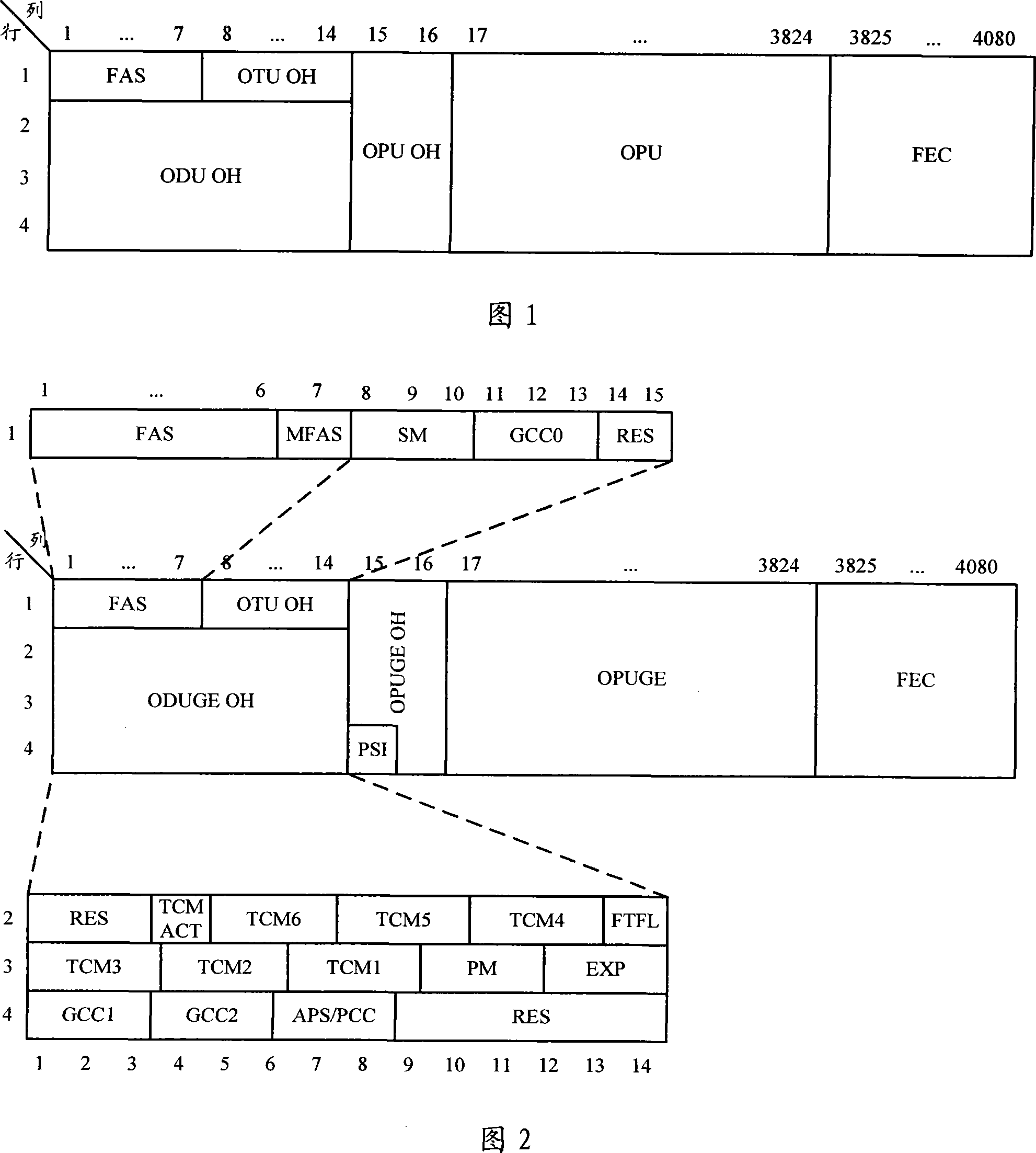
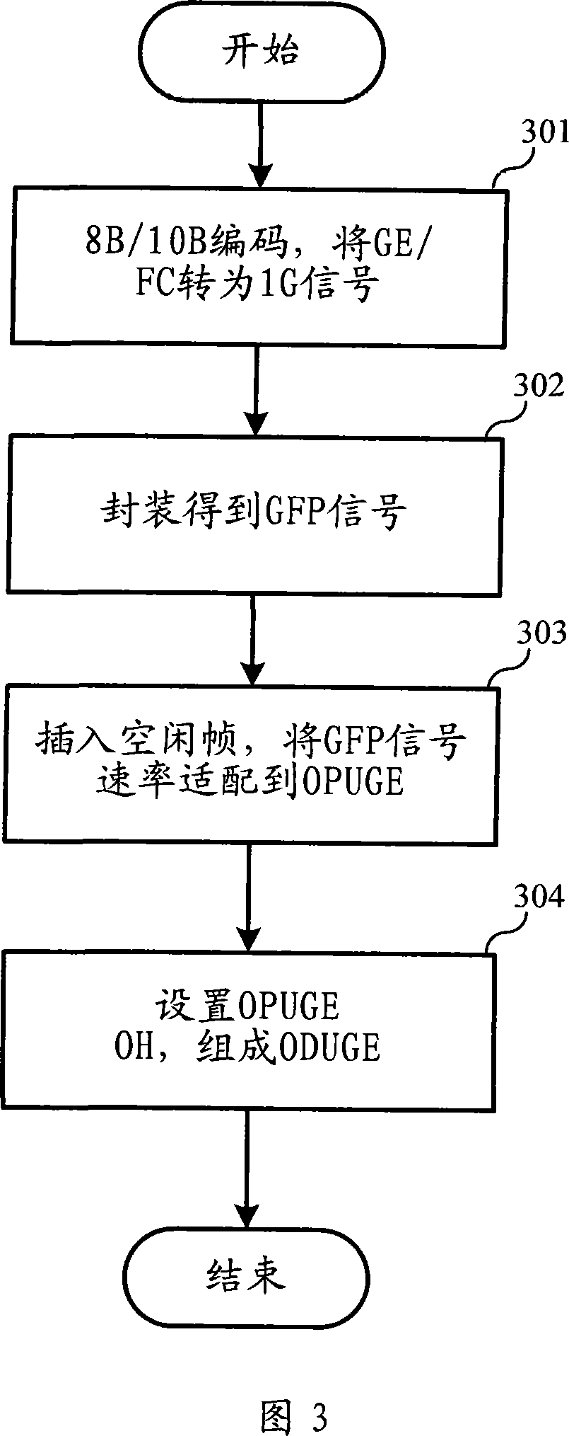
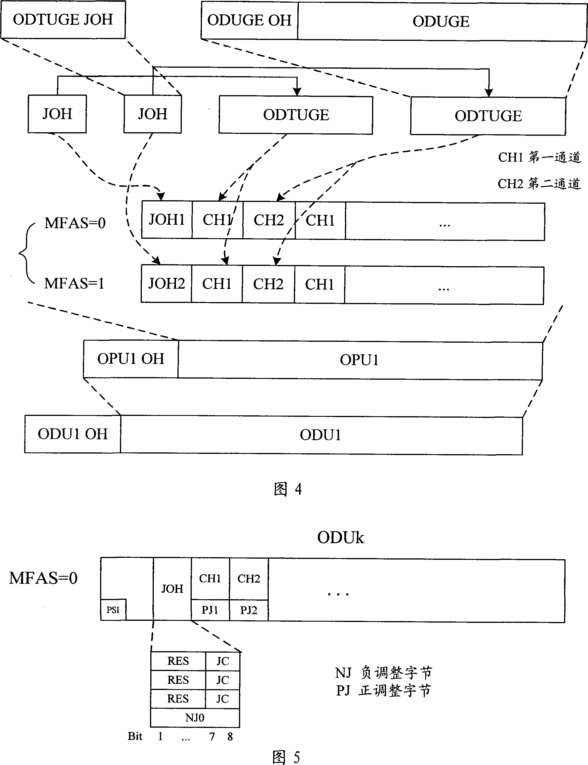
[0088] The present invention provides a mapping method for low-rate service signals such as GE and FC. On the basis of the existing ODUk connection function of OTN, a GE-level ODUGE connection function is added, so that GE or FC services can be used on the OTN network Flexible scheduling is realized on the network, and GE-level end-to-end performance management capability is provided; at the same time, the present invention provides an asynchronous multiplexing method from ODUGE to OPUk, so that the bandwidth utilization rate can be improved. The invention includes ODUGE frame structure definition, mapping method and its equipment, multi-service asynchronous multiplexing method and its equipment, ODUGE cross network device in OTN.

[0089] In one embodiment of the...


PUM


Abstract

The invention relates to the optical communication techniques and discloses a method and a device for transmitting low-speed business signals in an optical transmission network, which leads the low-speed business signal to be mapped onto the optical transmission network with high bandwidth utilization rate, can provide a flexible scheduling mechanism and an end-to-end performance management mechanism in a level of the low-speed business signal. The method and the device for transmitting the low-speed business signal in the optical transmission network adopt a GFP mapping method for mapping the low-speed business signal (GE / FC) to an ODUGE signal which is suitable for OTN transmission; the method and the device adopt an asynchronous or synchronous multiplexing method for multiplexing the ODUGE signal in multiple ways to one-way ODUk signal; the method and the device use the mapping from ODUGE to ODUk and an ODUGE cross network for implementing the on-line and off-line business in the level of the low-speed business signal .

Description

technical field [0001] The invention relates to the optical communication technology, in particular to the technology for transmitting low-rate service signals in the optical transmission network. Background technique [0002] With the development of information technology, various new services are rapidly entering people's lives, especially the explosive and rapid development of services based on Internet Protocol (Internet Protocol, referred to as "IP"), which not only makes people's lives greatly changed The changes, meanwhile, have profoundly affected every aspect of the telecommunications network. At present, the number of IP users in the world will reach more than 300 million. All of this will make the data traffic, especially the IP business, gradually replace the voice traffic and become the main traffic of the telecommunication network. This will inevitably lead to the transformation of the telecommunication network from the traditional telephone network. transitio...

Claims


Application Information

Patent Timeline
IPC IPC(8): H04J14/02H04L29/06H04B10/12H04B10/08H04J3/16H04Q11/00
CPCH04J3/1658H04J2203/0085
Inventor 邹世敏
Owner HUAWEI TECH CO LTD
Learn More