
A class D power amplifier and the corresponding input signal modulation method

A power amplifier, input signal technology, applied in amplifiers, amplifiers with semiconductor devices/discharge tubes, pulse combination modulation, etc., can solve the problems of high performance index of modulated output signal, no output pulse signal spectrum, and increased system cost, etc. , to achieve the effect of suppressing battery interference, improving THD+N, and improving power efficiency

Inactive Publication Date: 2008-07-09
SICHUAN PANOVASIC TECH
View PDF0 Cites 19 Cited by
  • Summary
  • Abstract
  • Description
  • Claims
  • Application Information

AI Technical Summary

Problems solved by technology

In order to ensure the performance index and stability of the modulation system, the implementation structure of the SDM modulation method is relatively complicated, but its output pulse signal spectrum does not have a fixed frequency modulation carrier, its EMI advantage is better than that of the PWM modulation method, and the performance of its modulated output signal Higher indicators
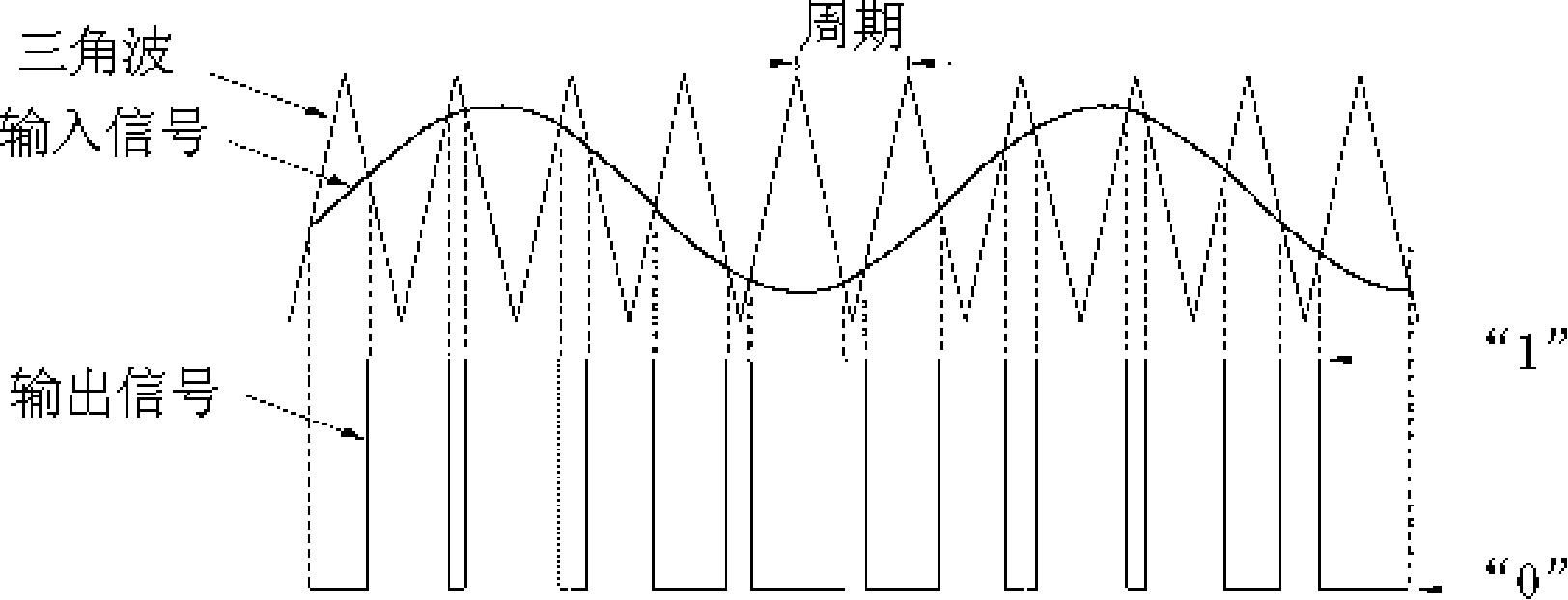
PWM and SDM modulation methods can be realized by analog or pure digital modulation methods. Analog modulation can use negative feedback to achieve higher performance indicators, but its input must be analog signals, which must be added to a large number of digital devices. High-precision digital-to-analog conversion devices increase system costs; the use of pure digital modulation methods can meet the requirements of modern digital trends, improve the accuracy of signal sources, directly amplify digital signals, reduce system costs, and increase many analog modulations that are not easy to achieve. Additional features

Method used


Image

  • A class D power amplifier and the corresponding input signal modulation method
  • A class D power amplifier and the corresponding input signal modulation method
  • A class D power amplifier and the corresponding input signal modulation method

Examples


Embodiment Construction

[0037] like Figure 5 As shown, the class D power amplifier of the present invention is composed of an SDM modulator, a data resampling circuit, a PWM modulator, a pulse shaping circuit, a power amplifier circuit, and a low-pass filter connected in sequence. The input signal first enters the SDM modulator for multi-level modulation, and the modulated signal enters the PWM modulator for three-level modulation after passing through the data resampling circuit. The level signal is transformed into a differential two-level pulse signal suitable for a BTL (Bridge Tied Load) power amplifier circuit.

[0038] like Figure 7 As shown, the SDM modulator is mainly composed of a noise shaping filter, a multi-level quantizer and a delay feedback loop. The delay feedback loop feeds back the level value output by the modulator to the noise shaping circuit. The main function of the SDM modulator is to modulate the input original signal into a multi-level output signal, and push the quantiz...


PUM


Abstract

The invention relates to a D-typed power amplifier, in particular to a D-type power amplifier and the input signal modulation technique. The invention discloses a D-typed power amplifier which can achieve balance between the system performance and the stability of the power amplifier and an input signal modulation method of the D-typed power amplifier. The D-typed power amplifier of the invention comprises a pulse density modulator, a pulse width modulator, a pulse molding circuit, a power magnify circuit and a low filter, and the pulse density modulator, the pulse width modulator, the pulse molding circuit, the power magnify circuit and the low filter are connected sequentially. The input signal modulation method of the D-typed power amplifier of the invention is: the signal is modulated in the pulse density aspect, the signal is modulated in the pulse width aspect, and the modulated signal is changed and is output to the power magnify circuit. The technical proposal of the invention is used for amplifying the power of the audio signal, thus efficiently improving the THD+N, SNR index and the power efficiency, and lowering the power magnify circuit of the switching frequency.

Description

technical field [0001] The invention relates to a class D power amplifier, in particular to a class D power amplifier and its input signal modulation technology. Background technique [0002] Traditional power amplifiers are divided into Class A, Class B and Class AB. Among them, the class A power amplifier works in the linear region of the power amplifier tube. Although the signal distortion is relatively small, the static point operating current is relatively large, and its power efficiency is usually only about 20%; the class B power amplifier uses a pair of power amplifier tubes to push-pull The signal is amplified in the form of a small static point operating current, but there is a serious crossover distortion near the zero crossing, and its power efficiency is usually only about 60%; the AB class power amplifier is based on the B class power amplifier Based on improvements, the signal distortion and static point operating current are between A and B power amplifiers,...

Claims


Application Information

Patent Timeline
IPC IPC(8): H03F3/217H03K7/10
Inventor 杨尚罡乔治L.杨王志辉
Owner SICHUAN PANOVASIC TECH
Learn More