
Multipolar bit fixture clamp

A tooling fixture and multi-pole technology, applied in the field of tooling fixtures, can solve problems such as low production efficiency, strong limitations of tooling fixtures, and poor safety, and achieve the effects of improving efficiency, breaking through single limitations, and being flexible and light in use

Active Publication Date: 2008-07-09
庄永杰 +1
View PDF0 Cites 1 Cited by
  • Summary
  • Abstract
  • Description
  • Claims
  • Application Information

AI Technical Summary

Problems solved by technology

[0003] In order to solve the problems existing in the above-mentioned traditional technology, the present invention designs a multi-pole tooling fixture after careful development and multiple experiments, which solves the problems of strong limitations, low production efficiency and poor safety of the tooling fixture in the prior art , and the operation process of the present invention is simple and easy, saving labor and time, low cost, and improving the utilization rate of the fixture

Method used


Image

  • Multipolar bit fixture clamp
  • Multipolar bit fixture clamp

Examples


Embodiment 1

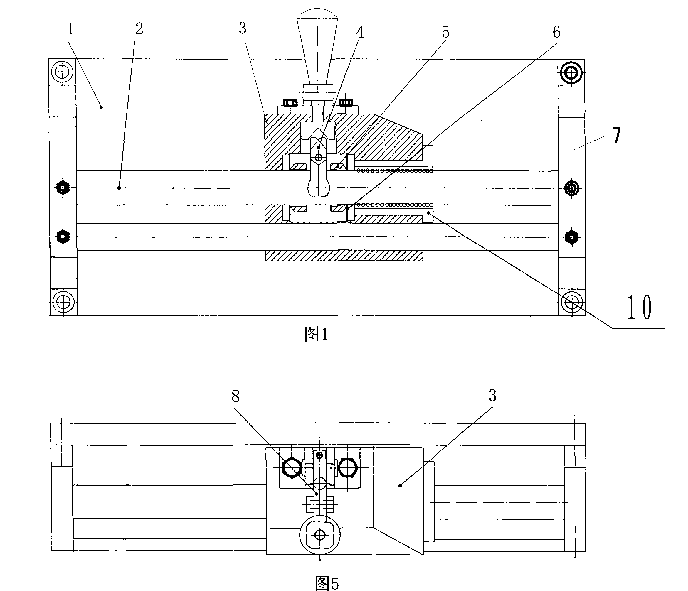
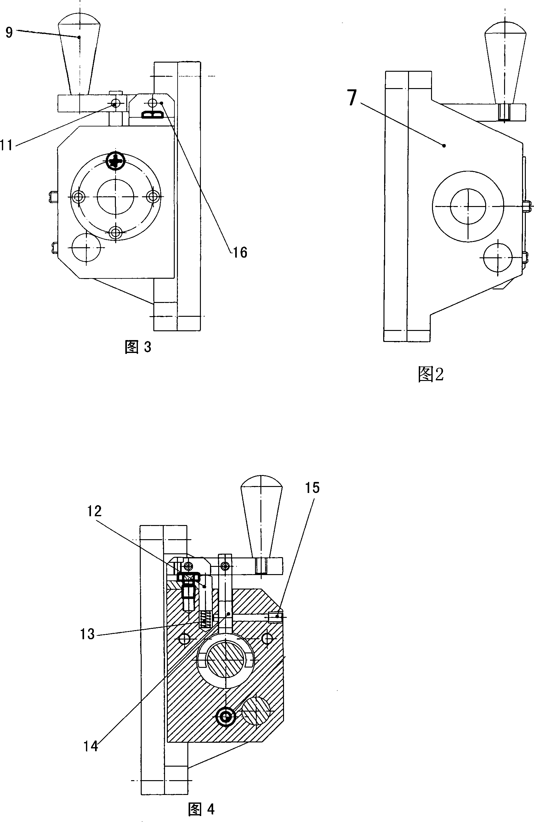
[0027] The base 1 is provided with a bracket 7, the two ends of the straight bar 2 are mounted on the bracket 7, the straight bar 2 is slidably provided with a guide body 3 through a linear bearing 10, and a V-shaped iron 14 is connected to the guide body 3 through a pin shaft 15. The upper end of the shaped iron 14 is fixedly connected with the pulling iron 8 through the pin shaft 11, one end of the pulling iron 8 is connected with the pulling handle 9, the other end of the pulling iron 8 is inserted into the socket 16, and the bottom end of the V-shaped iron 14 is provided with There is an opening and closing plug 4 , and steel sheets 6 are respectively provided on both sides of the opening and closing plug 4 through the plugging sleeve 5 . The guide body 3 is provided with a push rod 12 , the upper extending end of the push rod 12 is in active contact with the pulling iron 8 , and the lower end of the push rod 12 is connected with a spring 13 arranged inside the guide body 3...

Embodiment 2

[0029] The guide body 3 is provided with a cylinder or a hydraulic oil cylinder for automatic control, and other structures are the same as those in Embodiment 1.

[0030] The working process of the present invention is as follows:

[0031] When working, pull the handle 9 to start the pull-down, transmit power to the pulling iron 8, and the pulling iron 8 drives the V-shaped iron 14, forcing the puller 4 to separate, and the puller 4 pushes the two-way synchronous steel sheet 6 on both sides through the pusher sleeve 5 to slide. . When it is not fixed, the spring 13 bounces up the top rod 12, so that the pulling iron 8 pushes the pulling handle 9 to lift away.

[0032] When the workpiece is not in motion, that is, in a fixed position, the tooling can be equipped with a cylinder and a hydraulic cylinder, and the actuator can be operated automatically.


PUM


Abstract

The present invention relates to a multi-extreme position tooling clamp, which is applicable to the processing production of manifold workpieces. In the structure, both ends of each straight bar are mounted on a bracket, a guide body is slidingly arranged on the straight bars via a linear bearing, and an opening-and-closing device is arranged on the guide body. The structure of the present invention is simple, the operation is simple and easy, the use is flexible and convenient, and moreover, the present invention is applicable to the tooling production of manifold workpieces, increases the utilization rate of the clamp, reduces the economic pressure and saves energy and time.

Description

technical field [0001] The invention relates to a tooling fixture, in particular to a multi-pole tooling fixture, which is suitable for the processing and production of various workpieces. Background technique [0002] In the prior art, there are a variety of fixtures, such as special fixtures for the automotive industry, milling machine fixtures, welding fixtures and machining fixtures, etc. These fixtures are highly targeted and can only be limited to their own specific workpieces. It is used during processing, so the production cost of the workpiece is increased, and the operation is cumbersome. In addition, most of the clamps in the prior art are tightened by rotating, which makes the processing and production time-consuming and low in efficiency. Moreover, when the fixture is installed, it can only be fixed in the same position and cannot be moved, which increases the danger of the workpiece in the long-closed state. SUMMARY OF THE INVENTION [0003] In order to sol...

Claims


Application Information

Patent Timeline
Patent Type & Authority Applications(China)
IPC IPC(8): B23Q3/06
Inventor 庄永杰
Owner 庄永杰
Learn More