Discharge tube connector

A discharge tube and connector technology, which is applied in the field of discharge tube connectors, can solve the problems of difficult assembly, time-consuming, labor-intensive, etc., and achieves the effect of eliminating welding operations.

Inactive Publication Date: 2008-07-02
POLYMATECH CO LTD
View PDF2 Cites 3 Cited by
  • Summary
  • Abstract
  • Description
  • Claims
  • Application Information

AI Technical Summary

Problems solved by technology

However, in the invention described in JP Unexamined Publication No. 5-165085, the elastic metal plate connected to the electrodes must be welded to the circuit board. In addition, in the invention described in JP Unexamined Publication No. 8-297312, Electrodes and flat terminals are welded together
These welding operations are time-consuming and labor-intensive, so although the damage to the flash discharge tube 1 can be reduced, the assembly work is difficult.

Method used


Image

  • Discharge tube connector
  • Discharge tube connector
  • Discharge tube connector

Examples


Embodiment Construction

[0051] Hereinafter, embodiments of the present invention will be described with reference to the drawings. Reference numerals in the drawings indicate parts or components. In addition, redundant descriptions of configurations, materials, manufacturing methods, and the like that are common to the respective embodiments are omitted.

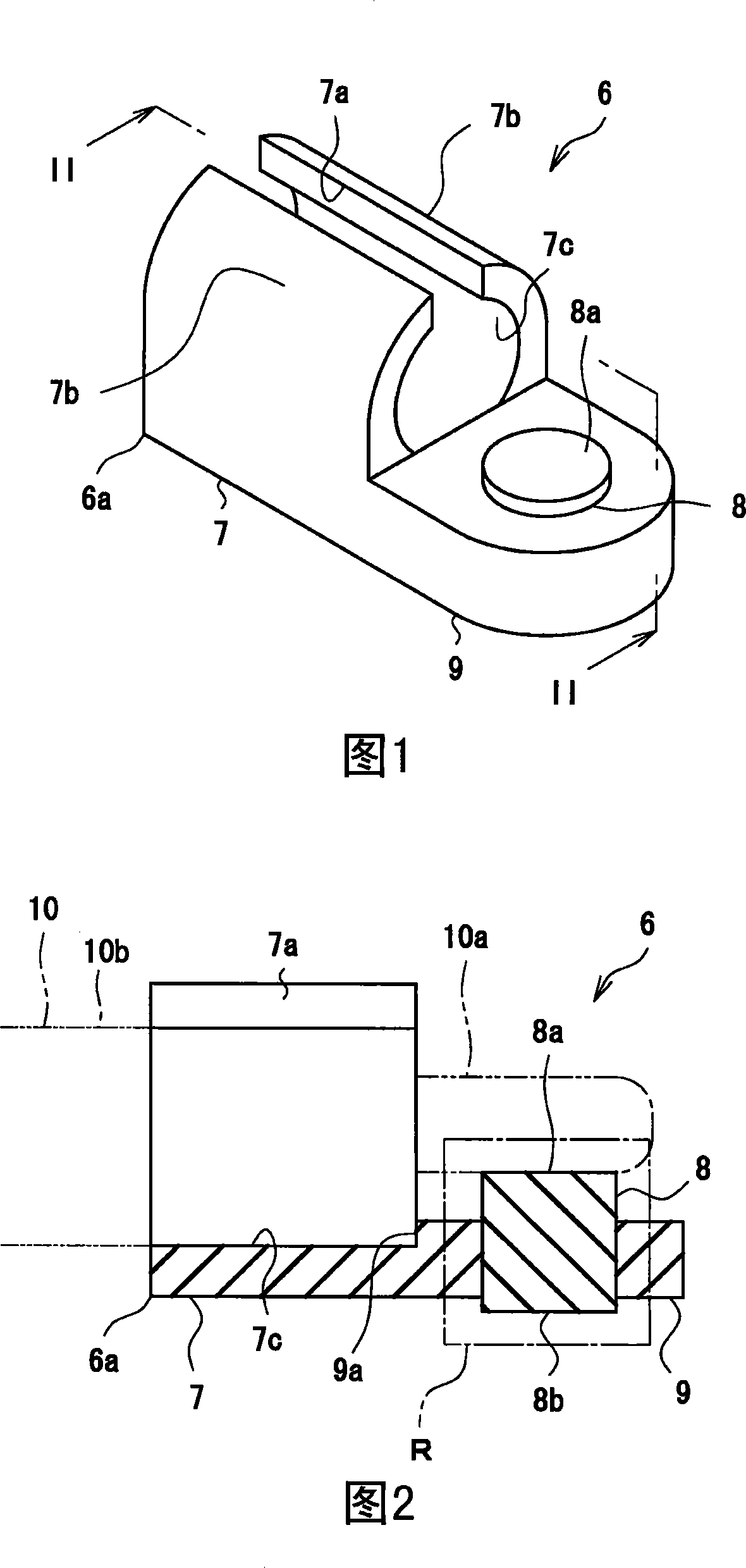
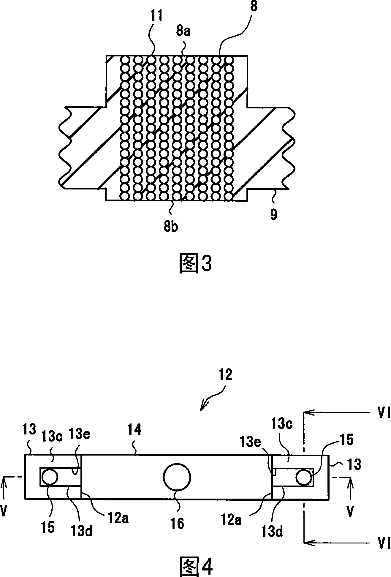
[0052] First Embodiment {FIGS. 1 to 3}: FIGS. 1 to 3 show a discharge tube connector 6 according to a first embodiment. FIG. 1 is a perspective view of a discharge tube connector 6 according to this embodiment, FIG. 2 is a sectional view taken along line II-II in FIG. 1 , and FIG. 3 is an enlarged sectional view of a portion R in FIG. 2 . The discharge tube connector 6 has a holding portion 6a attached to the end of the discharge tube 10, and the holding portion 6a has: a locking surface 7 that holds the light emitting tube 10b of the discharge tube 10; The face part 7 protrudes along the end electrode 10a; the conductive connection part 8 is pro...


PUM


Abstract

The present invention provides a discharge tube connector which suppresses the occurrence of a damage of a discharge tube at the time of installation and can be easily installed. An end electrode (10a) of the discharge tube (10) and a board electrode on a circuit board can be electrically connected with each other through a conductive connection portion (8) without using lead wires, so a damage such as a crack and the like, of a light-emitting portion (10b) of the discharge tube (10) can be avoided. When a holding portion (6a) is made of a rubber-like elastic material, the conductive connection portion (8) has rubber-like elasticity, so the conductive connection portion (8) can be pressed between the end electrode (10a) and the board electrode on the circuit board to conductively connect the end electrode (10a) with the board electrode. Therefore, the soldering operation can be omitted. Thus, installation does not take time, so a manufacturing cost can be reduced.

Description

technical field [0001] The present invention relates to a discharge tube connector for electrically connecting a discharge tube such as a flash discharge tube to a current substrate and holding the discharge tube. Background technique [0002] Many lighting devices have a discharge tube as a light source. For example, a flash device used for camera photography has a straight tube-shaped flash discharge tube, a circuit board, and a reflector, and condenses light emitted by the flash discharge tube onto the reflector to illuminate a subject. A conventional example of such a flash device is specifically described using FIG. 25. In this flash device, an end electrode 2a protruding from a light-emitting portion 2b of a flash discharge tube 1 as a pin terminal is inserted and held so as to surround the flash discharge tube. The reflector 3 provided in the form of the tube 1 is connected electrically by soldering the lead wire 4 extending from the end electrode 2a to the circuit b...

Claims


Application Information

Patent Timeline
Patent Type & Authority Applications(China)
IPC IPC(8): F21V23/06
CPCG03B15/05H01J5/50G03B2215/056H04N23/56
Inventor 池田匡宏今野英明
Owner POLYMATECH CO LTD
Why Eureka
Try Eureka