
Excretion exhaust apparatus of water closet

A technology for sewage discharge devices and toilets, applied in water supply devices, flushing equipment with water tanks, flushing toilets, etc., can solve the problem of reducing the up and down moving distance of the up and down moving mechanism, reducing the overall volume of the toilet, and reducing the weight of the up and down movable sewage pipe Water storage bags and other problems, to achieve the effect of small size

Inactive Publication Date: 2008-07-02
李永镐
View PDF0 Cites 6 Cited by
  • Summary
  • Abstract
  • Description
  • Claims
  • Application Information

AI Technical Summary

Problems solved by technology

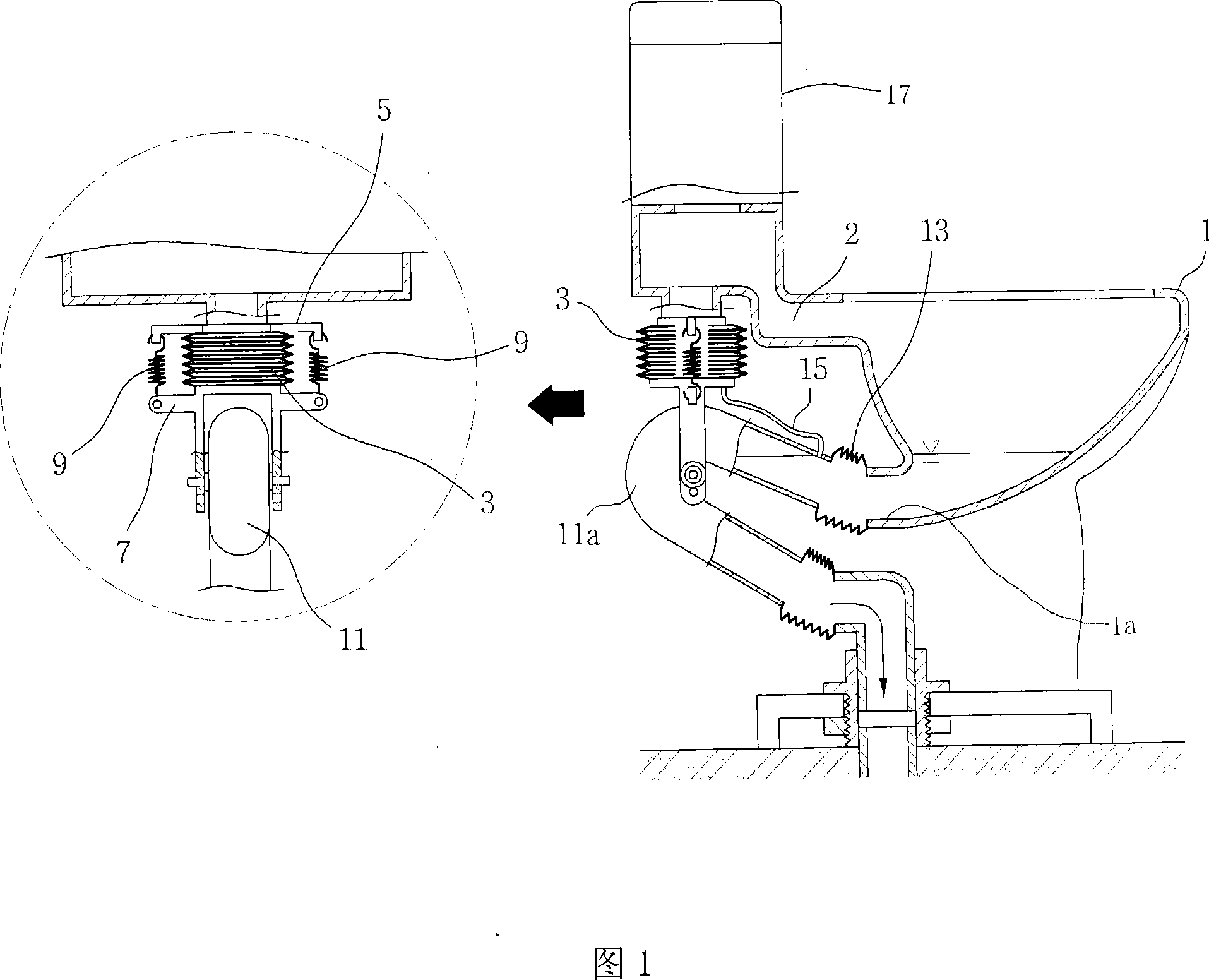
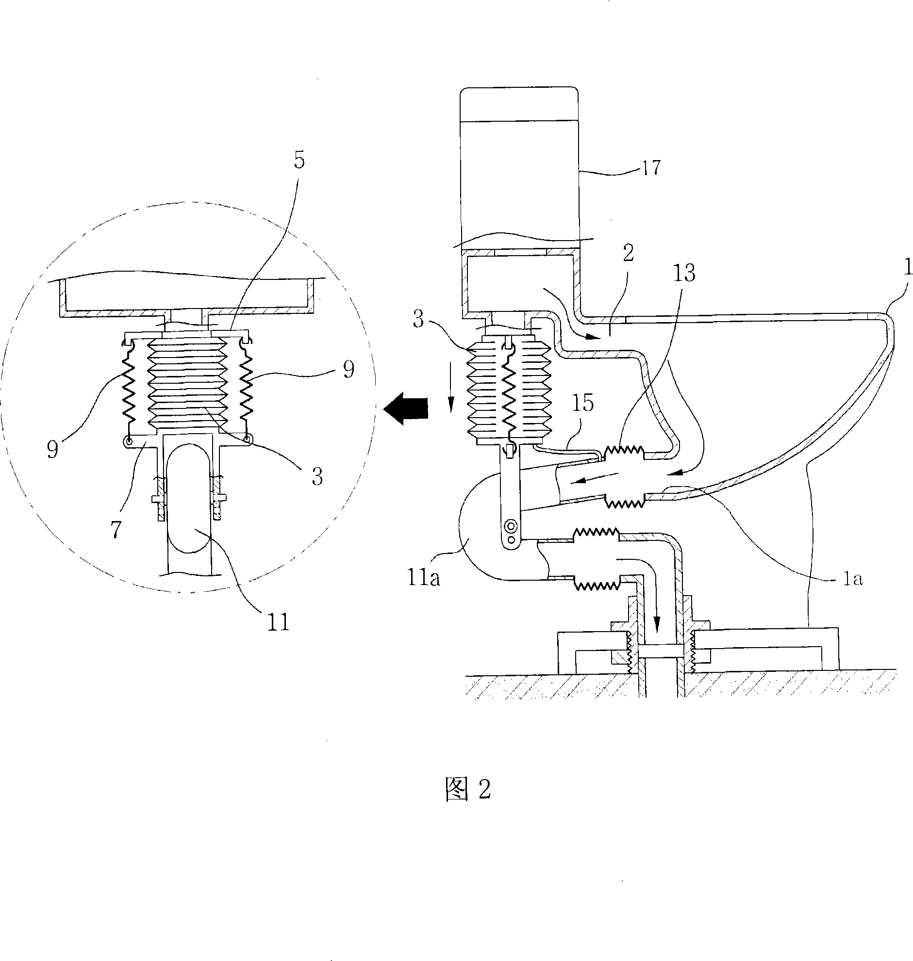
[0021] The purpose of the present invention is to solve the above problems. Its purpose is to provide a sewage discharge device for toilet. By optimizing the installation position of the up and down movement mechanism of the sewage pipe, the up and down movement distance of the up and down movement mechanism can be reduced as much as possible, so that the water tank can be reduced. Set the location and reduce the overall volume of the toilet, and the product (toilet) meets the requirements of advanced and simple structure, and because the up and down movable sewage pipe is changed from the existing U-shaped pipe to a straight line, it can significantly reduce the up and down movement. The weight of the sewage pipe reduces the capacity of the water storage bag, increases the water supply volume of the toilet seat and improves the flushing capacity, and the straight line adopted completely avoids the phenomenon of contact with the toilet floor by using a closed shield, It solves the inconvenience caused by the exposure of the sewage pipe moving up and down to the user, and overcomes the lack of durability of the connecting bellows caused by the contact with the ground of the toilet when the existing mobile sewage pipe in the shape of a U-shaped pipe moves up and down. The problem

Method used


Image

  • Excretion exhaust apparatus of water closet
  • Excretion exhaust apparatus of water closet
  • Excretion exhaust apparatus of water closet

Examples


Embodiment Construction

[0043] Hereinafter, preferred embodiments of the present invention will be described in detail with reference to the accompanying drawings.

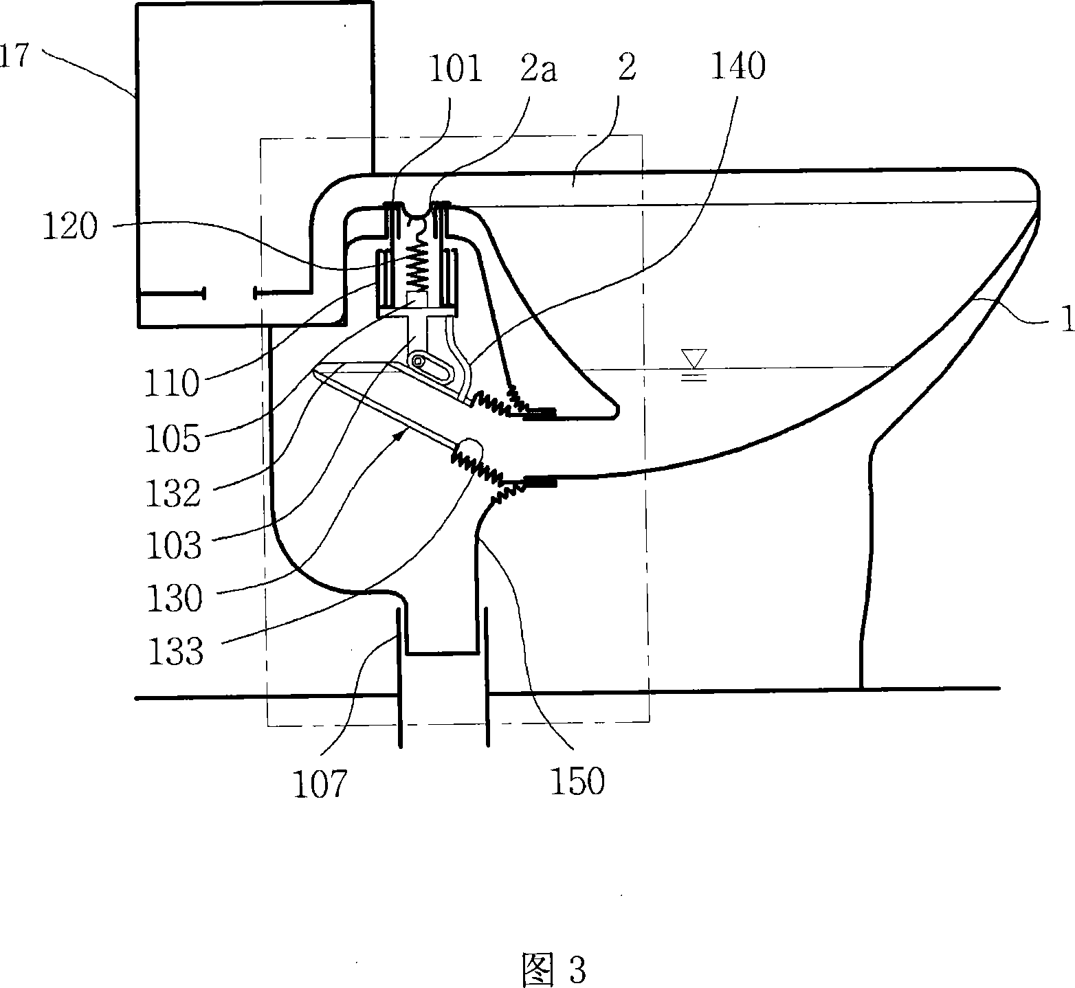
[0044]Fig. 3 is a schematic diagram of the state before the action of the sewage discharge device in the toilet of the present invention; Fig. 4 is a detailed schematic diagram of the state before the action of the sewage discharge device in the toilet of the present invention; Fig. 5 is in the toilet of the present invention, A schematic diagram of the state of the sewage discharge device after it is activated; Figure 6 is a detailed schematic diagram of the state of the sewage discharge device after the action of the toilet of the present invention; Figure 7 is a comparison of the amount of movement between the existing mobile sewage pipe and the mobile sewage pipe of the present invention Schematic diagram; Figure 8 is a detailed schematic diagram of the shield in the sewage device of the present invention.

[0045] As shown in the ac...


PUM


Abstract

The present invention relates to an excretion exhaust apparatus of water closet, which is connected to one end of a excretion pipe on the excretion exhaust apparatus body and can move up and down, to implement optimization design to the up-down movable mechanism to reduce up-down movable distance and lower tank position, so as to provide a higher excretion exhaust apparatus with simple structure.The shape of the up-down movable excretion pipe is changed from existing U-shaped pipe to straight line shape, which reduces the weight of the excretion pipe and the capacity of storage water bag, and increases the feed-water amount of the excretion exhaust apparatus and improves flushing force. The existing U-shaped excretion pipe can contact to the floor when moving up and down sometimes, thus the durability of a coupling bellows is not long, however, the draight line shape excretion pipe of the present invention avoids to contact to the closet ground using a closed shell. The excretion exhaust apparatus is composed of enclosed type shell, shrinking type storage water bag, tension spring, movable type excretion pipe and residual water comb for connecting the storage water bag and the movable type excretion pipe, the characteristic is that the up-down movable mechanism of the movable type excretion pipe is set between the tank and the closet seat.

Description

technical field [0001] The invention relates to a sewage discharge device of a toilet in which one end of a sewage pipe connected to a toilet seat can move up and down. The moving distance and the position of the water tank are lowered to provide a high-grade and simple structure product (toilet), and since the vertically movable sewage pipe is changed from the existing U-shaped pipe to a straight line, the weight of the vertically movable sewage pipe can be significantly reduced And the capacity of the water storage bag is reduced, and the water supply volume of the toilet seat body is increased, thereby improving the flushing force. The existing U-shaped movable sewage pipe sometimes touches the floor of the toilet when moving up and down, so the durability of the connecting bellows is not high. The cover avoids the phenomenon of being in contact with the ground of the closet, and solves the inconvenience to the user caused by the sewage pipe moving up and down. Backgroun...

Claims


Application Information

Patent Timeline
IPC IPC(8): E03D11/13E03D1/26
CPCE03D5/012E03D11/13
Inventor 李钟寅林俸均
Owner 李永镐
Learn More