
Continuous-blending muller

A grinding machine and mixing chamber technology, applied in the direction of mixers, fluid mixers, mixer accessories, etc., can solve the problems of small processing capacity, intermittent operation, complex process, etc., to reduce equipment investment and floor space, improve mixing Grinding efficiency and the effect of shortening the process flow

Active Publication Date: 2008-06-25
CHINA PETROLEUM & CHEM CORP +1
View PDF0 Cites 16 Cited by
  • Summary
  • Abstract
  • Description
  • Claims
  • Application Information

AI Technical Summary

Problems solved by technology

This method has the disadvantages of long process, complex process, intermittent operation, many equipment, small processing capacity, low efficiency, high energy consumption, etc., especially when mixing and grinding to prepare some colloids with high solid content, due to the existence of colloid mixing and Transportation and other difficulties, so it is difficult to prepare colloids with high solid content and fine particle size

Method used


Image

  • Continuous-blending muller
  • Continuous-blending muller
  • Continuous-blending muller

Examples


Embodiment 1

[0041] This embodiment illustrates: the continuous mixing-grinding machine provided by the present invention is used to uniformly mix solid powder and liquid and grind them into fine-grained colloids.

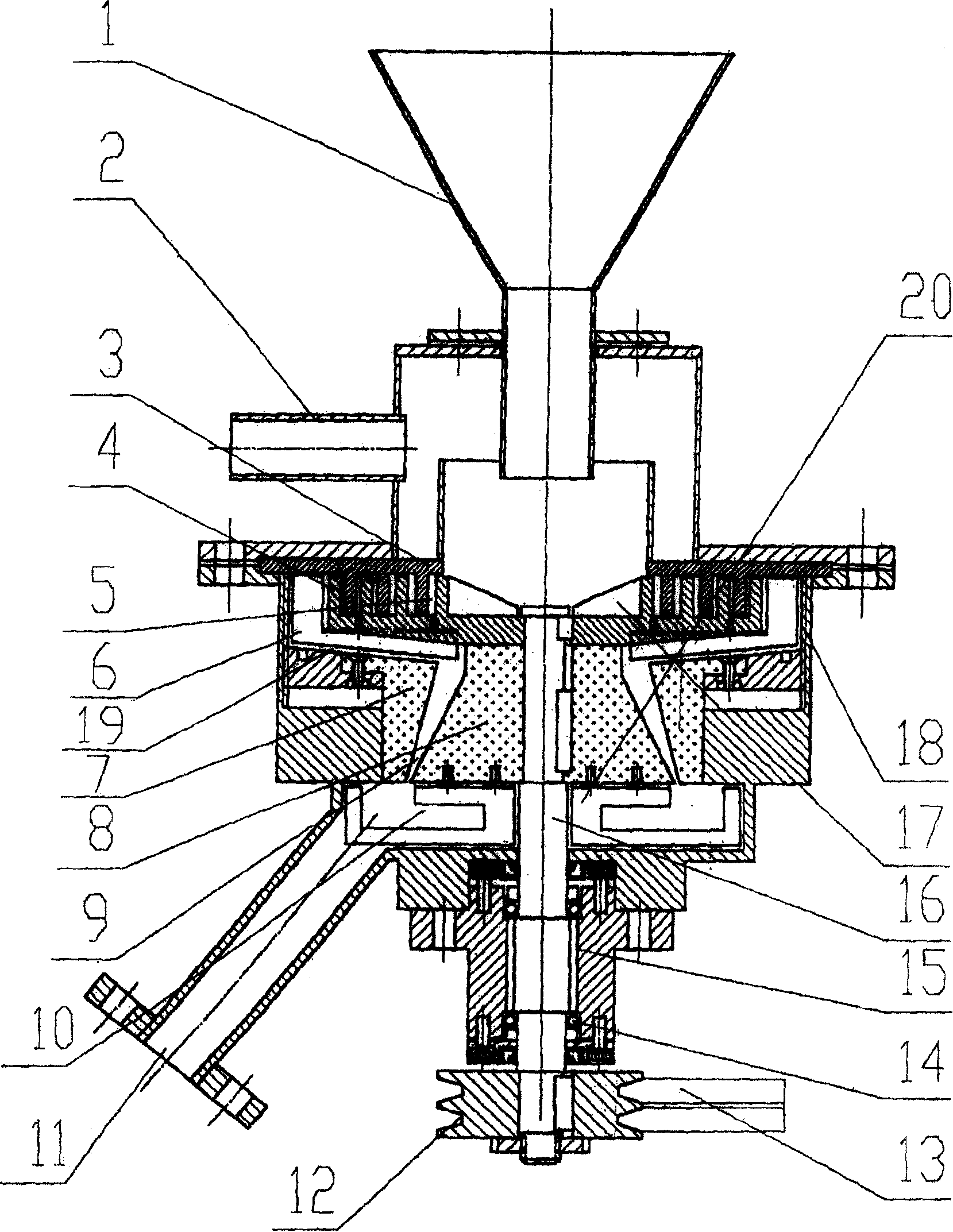
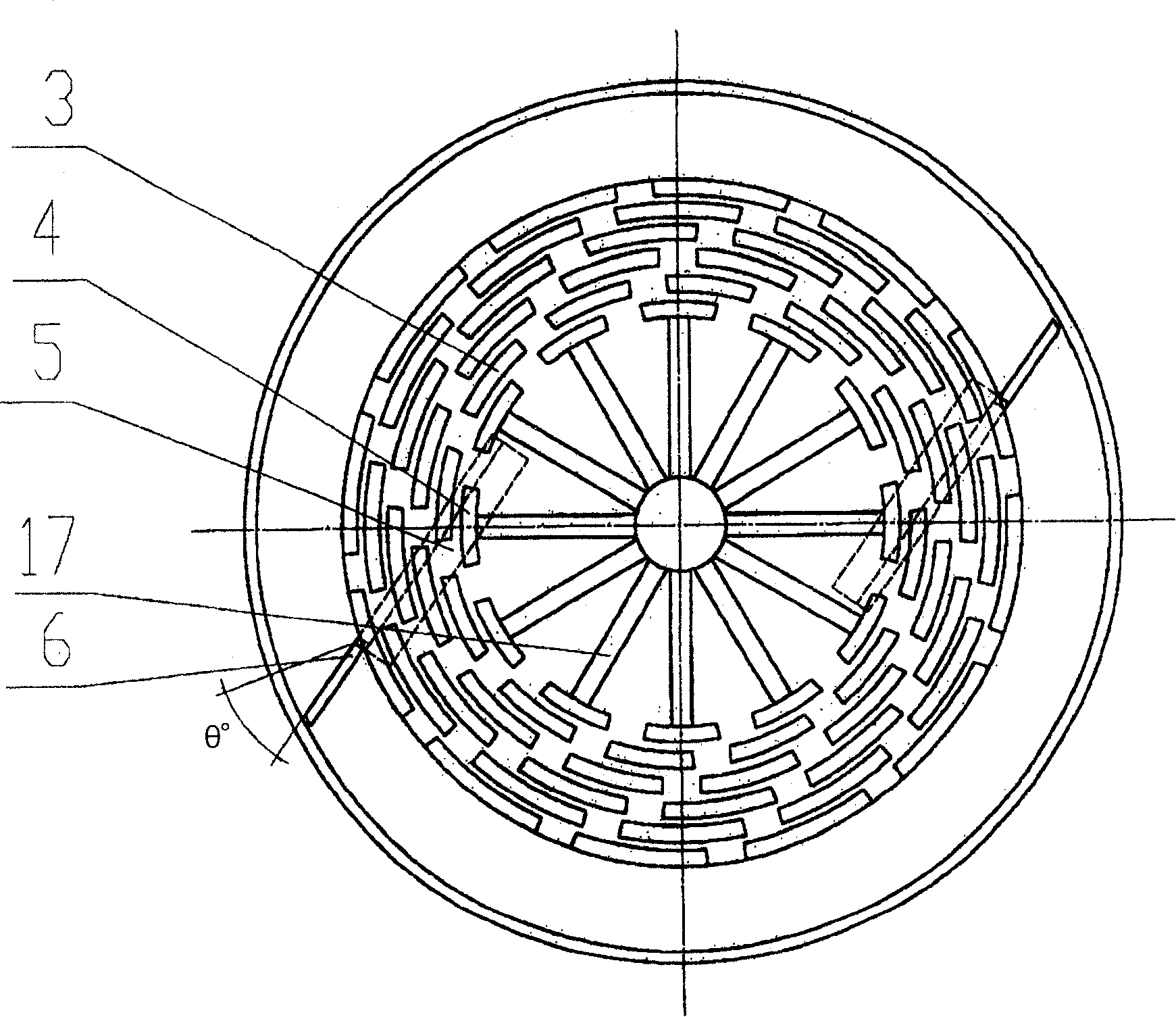
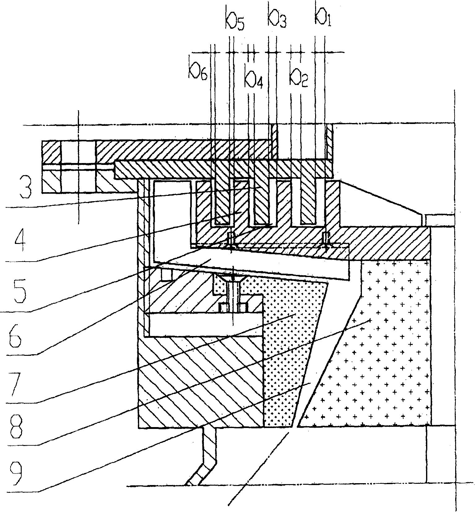
[0042] The structure of the continuous mixing-grinding machine adopted in the present embodiment is as follows: figure 1 Shown: the inner diameter of the mixing device shell is 200mm, the shell height is 450mm, the tooth height of the mixing stator 3 and the mixing rotor 4 is 20mm, the mixing stator 3 is composed of 3 layers of teeth, and the mixing rotor 4 is composed of 4 layers of teeth, each layer For 20 teeth. Radially outward from the center of the rotating shaft 16, the gaps between the teeth of the hybrid stator 3 and the teeth of the hybrid rotor 4 are respectively b1=3.5mm, b2=3.mm, b3=2.5mm, b4=b5=b6= 2.0mm. Two scrapers 6 symmetrically arranged on the bottom circumference of the mixing rotor 4 are used. The gap between the two scrapers 6 and the inner wall of the ...

Embodiment 2

[0047] In this example, the same continuous mixing-grinding machine as in Example 1 was used to grind the cracking catalyst fine powder. The source of the powder was the fine powder produced when the cracking catalyst was prepared in this laboratory, and the particle size distribution of the powder was 5-60 μm, wherein The average particle size is about 28 μm.

[0048] As a result, 400kg of colloid was produced, the solid content of the colloid was 40%, the particle size of the colloid was 0.8-5.5 μm, and the average particle size of the colloid was 1.8 μm. Two people were required to operate the system, the production time was 1.5 hours, the electricity consumption was 8.5 degrees, and the cleaning water Be 20 liters, use about 195kg of raw material (its solid content is about 84%).


PUM

PropertyMeasurementUnit
Granularityaaaaaaaaaa
Average particle sizeaaaaaaaaaa
Particle size distributionaaaaaaaaaa

Abstract

The invention provides a continuous mixing-grinding machine including a mixing device and a grinding device. The mixing device includes a feed inlet, a mixing stator, a mixing rotor, a mixing chamber and a material discharge space. The grinding device includes a grinding stator, a grinding rotor, a grinding chamber, an accumulating chamber and a colloid discharge opening; among which, the mixing device and the grinding device are coaxially arranged up and down and the material discharge space is communicated with the grinding chamber. The bottom of the mixing rotor is provided with a material scraping machine used for scraping the colloid on an inner wall of the mixing device and forcing the colloid to be discharged from the material discharge space and then enter the grinding chamber; and the bottom of the grinding rotor is provided with a material extrusion apparatus used for forcing the colloid to be discharged from the colloid discharge opening. The mixing-grinding machine provided by the invention can continuously manufacture the colloid with high solid content on line.

Description

technical field [0001] The invention relates to a continuous mixing-grinding machine, more specifically, to a continuous mixing-grinding machine which continuously mixes solid powder and liquid into a colloid, and directly grinds the colloid into a finer colloid. Background technique [0002] In the chemical industry, metallurgy, building materials, food and other industries, the process of colloid mixing and colloid grinding such as solid powder and liquid mixing, kneading, humidification, etc. is often encountered. These processes are basically firstly mixed intermittently in the stirred reactor to form colloids, and then the colloids are separately loaded into a colloid grinder to grind them into colloids of required particle size. This method has the disadvantages of long process, complex process, intermittent operation, many equipment, small processing capacity, low efficiency, high energy consumption, etc., especially when mixing and grinding to prepare some colloids w...

Claims


Application Information

Patent Timeline
IPC IPC(8): B02C2/10B01F5/12B01F5/16B01F15/02B01F15/00B01F25/60B01F25/64
Inventor 田志鸿周健吕庐峰张占柱李学锋王骞何金龙
Owner CHINA PETROLEUM & CHEM CORP
Learn More