
Whole optical fiber narrow linewidth hundred billisecond pulse signal system

A pulse signal and narrow linewidth technology, applied in cladding optical fiber, optics, lasers, etc., can solve the problems of pulse shape distortion, difficult coupling adjustment, limited fiber energy, etc., and achieve the effect of narrow linewidth and good stability

Inactive Publication Date: 2008-06-18
SHANGHAI INST OF OPTICS & FINE MECHANICS CHINESE ACAD OF SCI
View PDF0 Cites 7 Cited by
  • Summary
  • Abstract
  • Description
  • Claims
  • Application Information

AI Technical Summary

Problems solved by technology

[0003] Although the widely used large mode field fiber (LMF) can effectively reduce the power density in the fiber core, increase the nonlinear threshold, and achieve high power and distortion-free amplification of long-pulse signals, because the core diameter is above 10 μm, The transmission characteristics of the fundamental transverse mode of the beam during the amplification process cannot be guaranteed; while the ordinary single-mode fiber amplifier can guarantee the single transverse mode characteristic of the beam, but due to the limited energy that can be stored in the fiber, when a hundred nanosecond pulse is amplified, with The increase of signal power can easily saturate the amplifier gain and cause pulse shape distortion, which cannot meet the requirements of narrow line width, high power, fundamental transverse mode, single longitudinal mode and no distortion of pulse shape, for example, in inertial confinement fusion (ICF) In the process of developing the front-end drive system of the device in the direction of integration, not only high power and no distortion of the pulse shape are required before entering the beam splitter array, but also good beam quality, fundamental transverse mode and single longitudinal mode are required.
At the same time, many high-power amplifiers use a lens to couple signal light and pump light. The coupling adjustment is difficult, the coupling efficiency is low, the structure is unstable, and the environment is greatly affected. These shortcomings limit its application in many occasions.

Method used


Image

  • Whole optical fiber narrow linewidth hundred billisecond pulse signal system

Examples


Embodiment 2

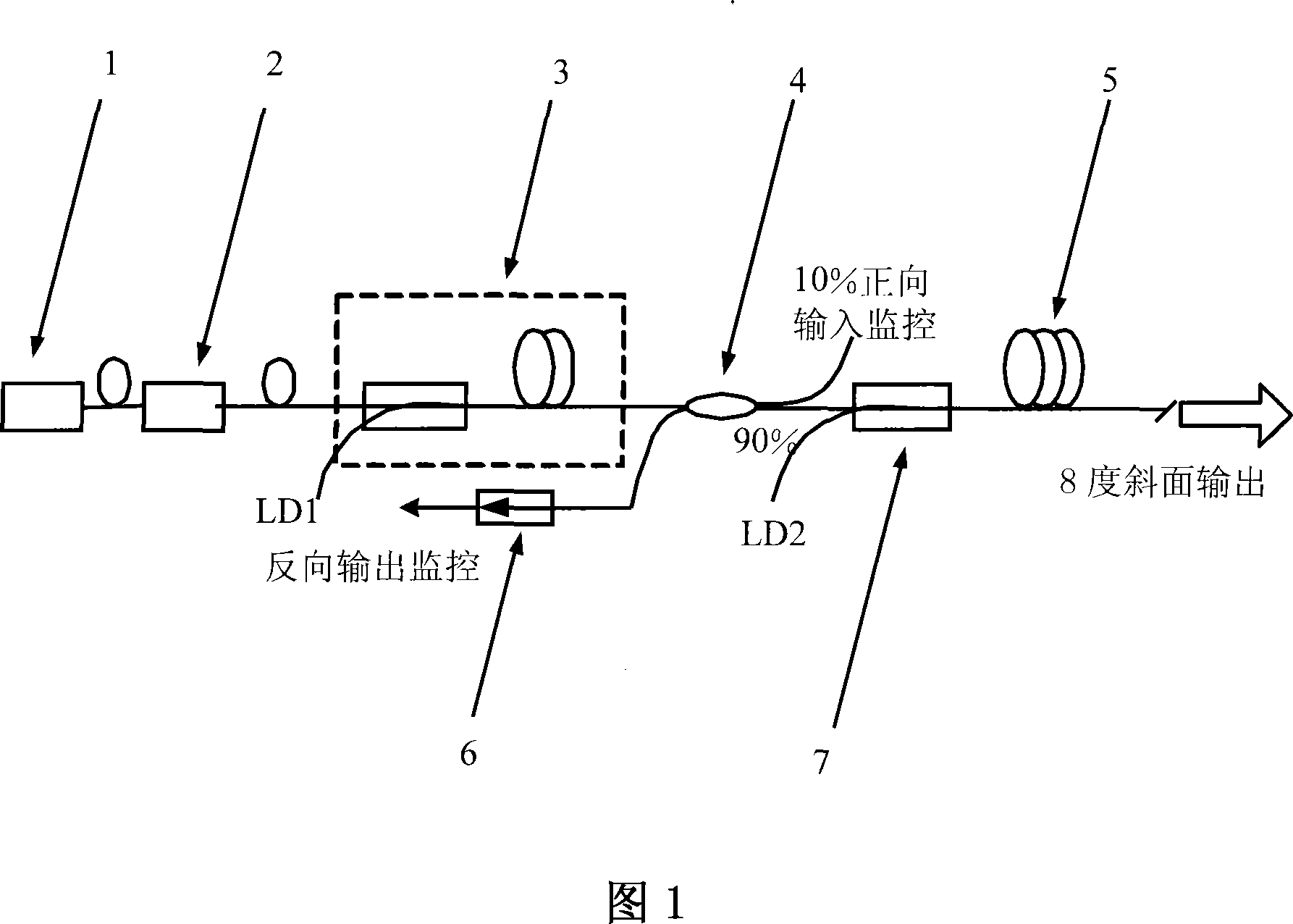
[0020] Embodiment 2, the difference compared with embodiment 1 is that the output terminal of described ytterbium-doped double-clad fiber amplifier 5 is connected to a high-power fiber isolator, such as a fiber isolator of > 3W, which can greatly improve the overall The stability of the system, the output structure of the fiber optic isolator is easier to package, and can meet the requirements of narrow line width, high power and output pulse waveform without distortion in more occasions.


PUM

PropertyMeasurementUnit
Diameteraaaaaaaaaa
Diameteraaaaaaaaaa
Diameteraaaaaaaaaa

Abstract

The invention provides a full optical fiber narrow linewidth hundred nanosecond pulse signal system; the invention comprises a distribution feedback optical fiber laser, an acoustic and optical chopper, a ytterbium-doped single mode fiber preamplifier, a fiber beam splitter; the 90 percent output end of the optical fiber beam splitter is melted with the signal end of a multimode pumped beam combiner, all of which are interconnected sequentially; the output tail optical fiber of the multimode pumped beam combiner is melted with the optical fiber of a ytterbium-doped doubly clad optical fiber amplifier; the pumped end of the multimode beam combiner is connected with a multimode semiconductor laser; the output end surface of the tail optical fiber of the ytterbium-doped doubly clad optical fiber amplifier is provided with an inclined plane of eight degrees and the backward output monitoring end of the optical fiber beam splitter is connected with an optical fiber isolator. The amplified pulse signal of the invention has the advantages of narrow linewidth, fundamental transverse mode, single longitudinal mode, good stability and no deformation of the pulse shape under high power and the pulse signal is easy to be enclosed and can not be affected by environment significantly.

Description

technical field [0001] The invention relates to laser, especially a kind of all-fiber narrow-linewidth hundred-nanosecond pulse signal system, which is a hundred-nanosecond pulse laser signal source realized by using ytterbium-doped double-clad fiber. Its advantages are good beam quality, narrow Line width, fundamental transverse mode, single longitudinal mode, and in the case of high power, the 200ns square wave has almost no distortion. This system can be applied to occasions that have strict requirements on line width, power and pulse shape at the same time. Background technique [0002] The signal source module implemented by optical fiber has the advantages of good beam quality, high efficiency, high stability, and compact structure, and has been widely used in communication, industry, and medical fields. Ytterbium doped (Yb 3+ ) silica fiber belongs to a simple two-level structure, with wide absorption spectrum, gain bandwidth and tuning range, high quantum efficiency...

Claims


Application Information

Patent Timeline
IPC IPC(8): G02F1/35H01S3/00G02B6/02G02B6/26
Inventor 常丽萍陈柏王江峰陈嘉琳王利李国扬林尊琪
Owner SHANGHAI INST OF OPTICS & FINE MECHANICS CHINESE ACAD OF SCI
Learn More