Eureka AIR delivers breakthrough ideas for toughest innovation challenges, trusted by R&D personnel around the world.

Fluid flow control system of gas foaming agent

A flow control and gas foaming technology, applied in flow control, control/regulation systems, non-electric variable control, etc., to solve problems such as unstable flow measurement

Active Publication Date: 2008-06-18
BEIJING CHN TOP MACHINERY
View PDF2 Cites 18 Cited by
  • Summary
  • Abstract
  • Description
  • Claims
  • Application Information

AI Technical Summary

Problems solved by technology

However, when using this method, on the one hand, the relationship between the pressure difference and the flow rate is not linear, and it is difficult to precisely control the flow rate only considering changing the pressure difference; on the other hand, the fixed orifice can only be controlled within a narrow range. Control the flow. After exceeding this range, the flow measurement is unstable. The technology disclosed in this patent application has obvious limitations in application.

Method used


Image

  • Fluid flow control system of gas foaming agent
  • Fluid flow control system of gas foaming agent

Examples


Embodiment Construction

[0010] Below in conjunction with accompanying drawing, feature of the present invention and related features are further described by embodiment:

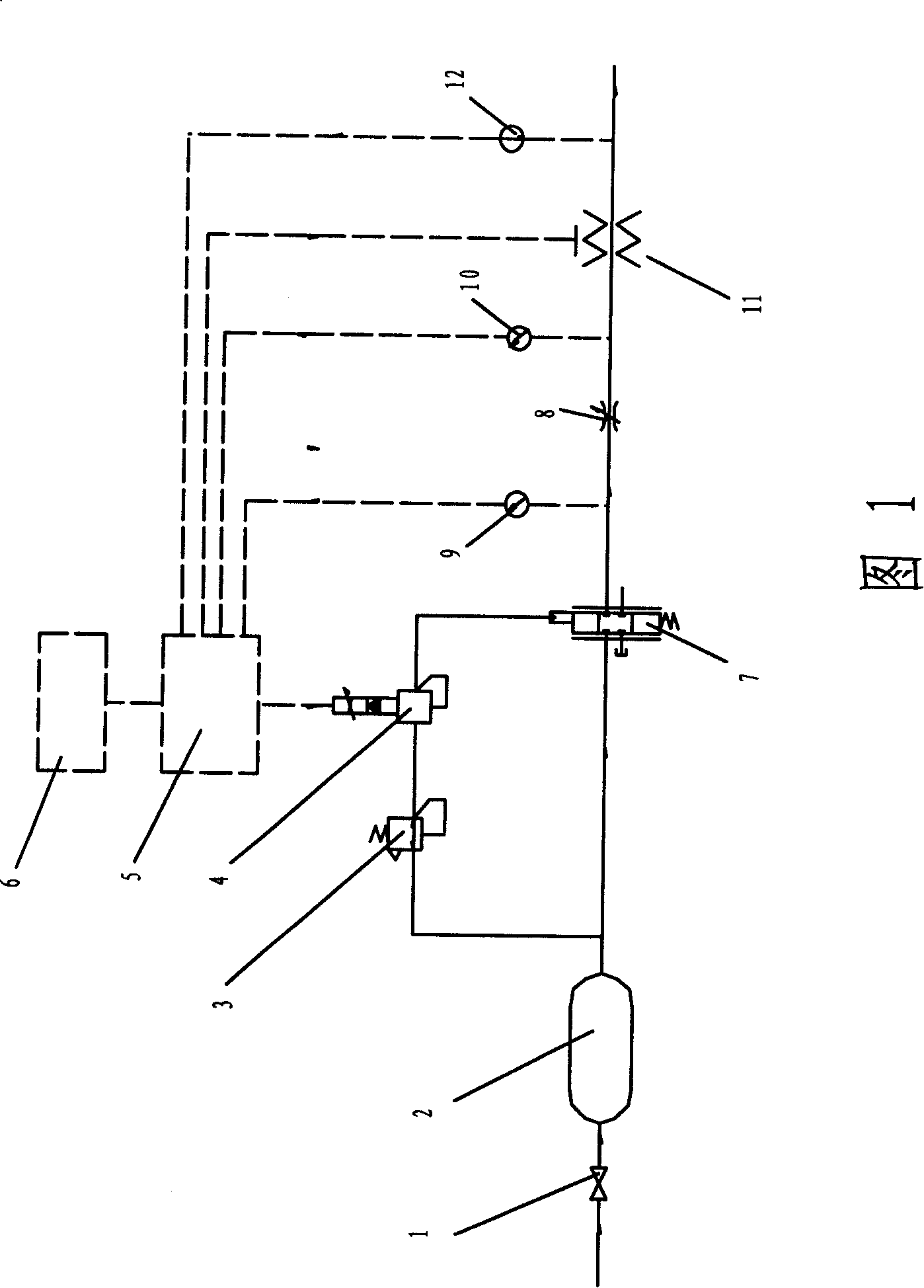
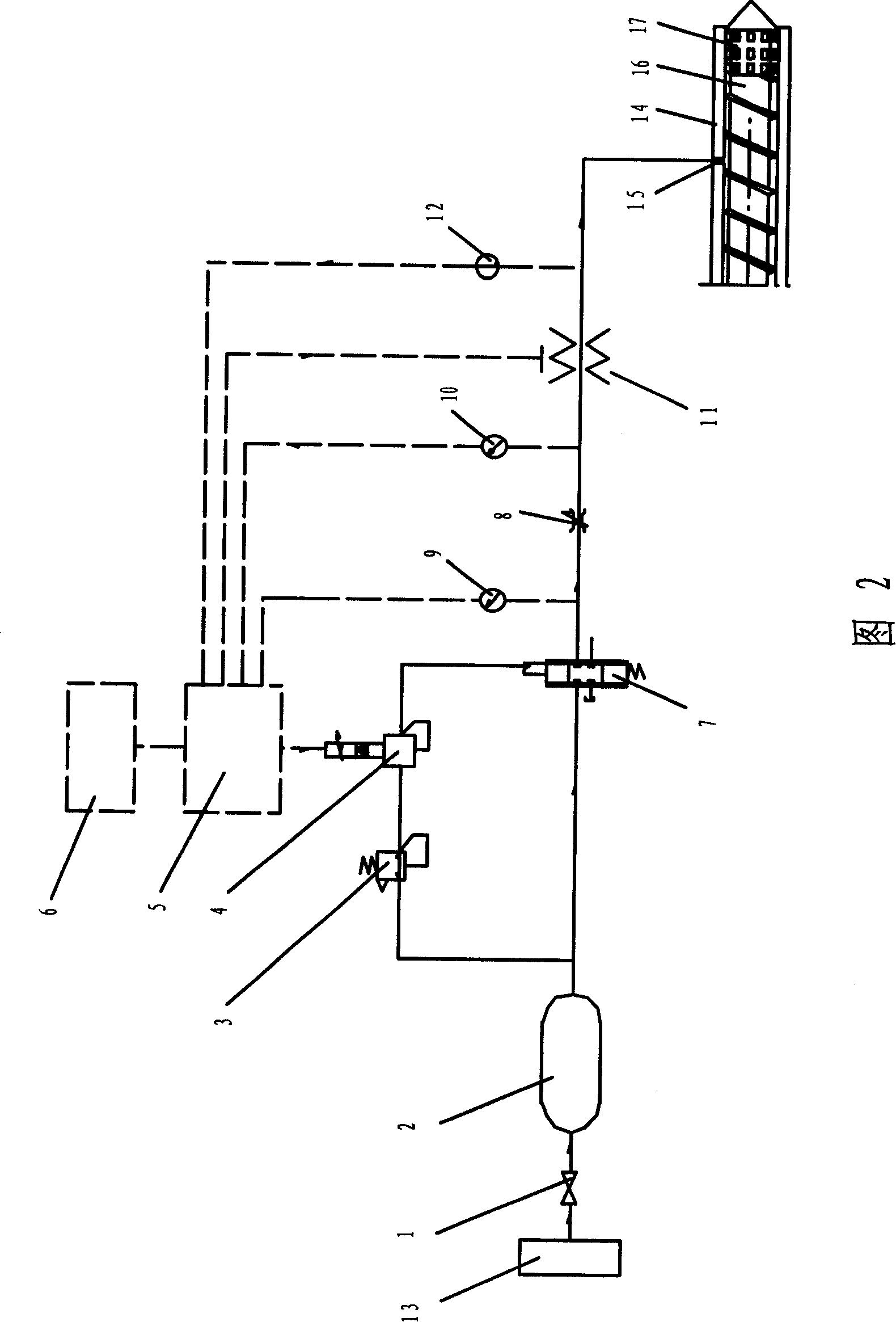
[0011] As shown in Figures 1 and 2, the labels 1-17 represent respectively, 1-stop valve, 2-high pressure container, 3-pressure reducing valve, 4-electromagnetic proportional valve stop valve, 5-data processing and control module, 6- Operation interface, 7-high pressure servo valve, 8-adjustable throttle valve, 9 and 10-pressure sensor, 11-foaming agent temperature control module, 12-temperature sensor, 13-high pressure air source, 14-resin processing device Barrel, 15-foaming agent inlet, 16-screw, 17-mixing element.

[0012] As shown in accompanying drawings 1 and 2, the system of the present invention includes an inlet shut-off valve 1, a high-pressure container 2, a pressure reducing valve 3, an electromagnetic proportional valve 4, a high-pressure servo valve 7, an adjustable throttle valve 8, pressure sensors 9 and 10, Foami...


PUM


Abstract

The invention relates to a control system and control method for the flow of a gas foaming agent, in particular to a control system for the flow of the foaming agent when a physical gas foaming agent is adopted for the processing of thermoplastic foam. The control system of the flow of gas foaming agent described in the invention comprises a stop valve 1, a high pressure vessel 2, a pressure reducing valve 3, a proportional solenoid valve 4, a high voltage servo valve 7, an adjustable throttle valve 8, pressure sensors 9 and 10, a foaming agent temperature control module 11, a temperature sensor 12, a data processing and control module 5, an operation interface 6, pressure conduits connecting the above components, and communication wires or cables. The invention has the advantages that in accordance with the set flow and temperature value of the foaming agent injected into a processing device, with the system of the invention, a closed loop is adopted to control the flow and temperature of the flow agent. Therefore, the foaming agent flow required in the foaming process can be precisely and uniformly led into a polymer.

Description

technical field [0001] The invention relates to a control system and method for the flow rate of a gas blowing agent, and more particularly to a control system for the flow rate of the blowing agent when using a gas physical blowing agent to process thermoplastic foam. Background technique [0002] Or due to structural needs, or due to functional needs such as heat insulation, sound insulation, etc., or for the purpose of saving raw material costs, more and more thermoplastic foam molding products are used. In foam molding, such as extrusion, injection or other molding methods, a known method is to use a chemical foaming agent to mix with a thermoplastic resin, and strictly control the process parameters. However, when using chemical foaming agents, on the one hand, the process control is very strict, on the other hand, there are foaming agent residues in the product, mold corrosion, and the subsequent use of the product is limited by environmental requirements, so more and ...

Claims


Application Information

Patent Timeline
Patent Type & Authority Applications(China)
IPC IPC(8): B29C44/60B29C44/34G05D7/00
Inventor 唐庆华桓锁成侯珏谢东海
Owner BEIJING CHN TOP MACHINERY
Why Eureka
Eureka Blog
Learn More