
Partial stroke testing system

a testing system and partial stroke technology, applied in the direction of measuring devices, instruments, using mechanical means, etc., can solve the problems of reducing the frequency of shutdown, not providing for the testing of the shut-off valve itself, and unfavorable conditions

Inactive Publication Date: 2002-08-15
ALBUAIJAN TAREQ NASSER
View PDF0 Cites 75 Cited by
  • Summary
  • Abstract
  • Description
  • Claims
  • Application Information

AI Technical Summary

Benefits of technology

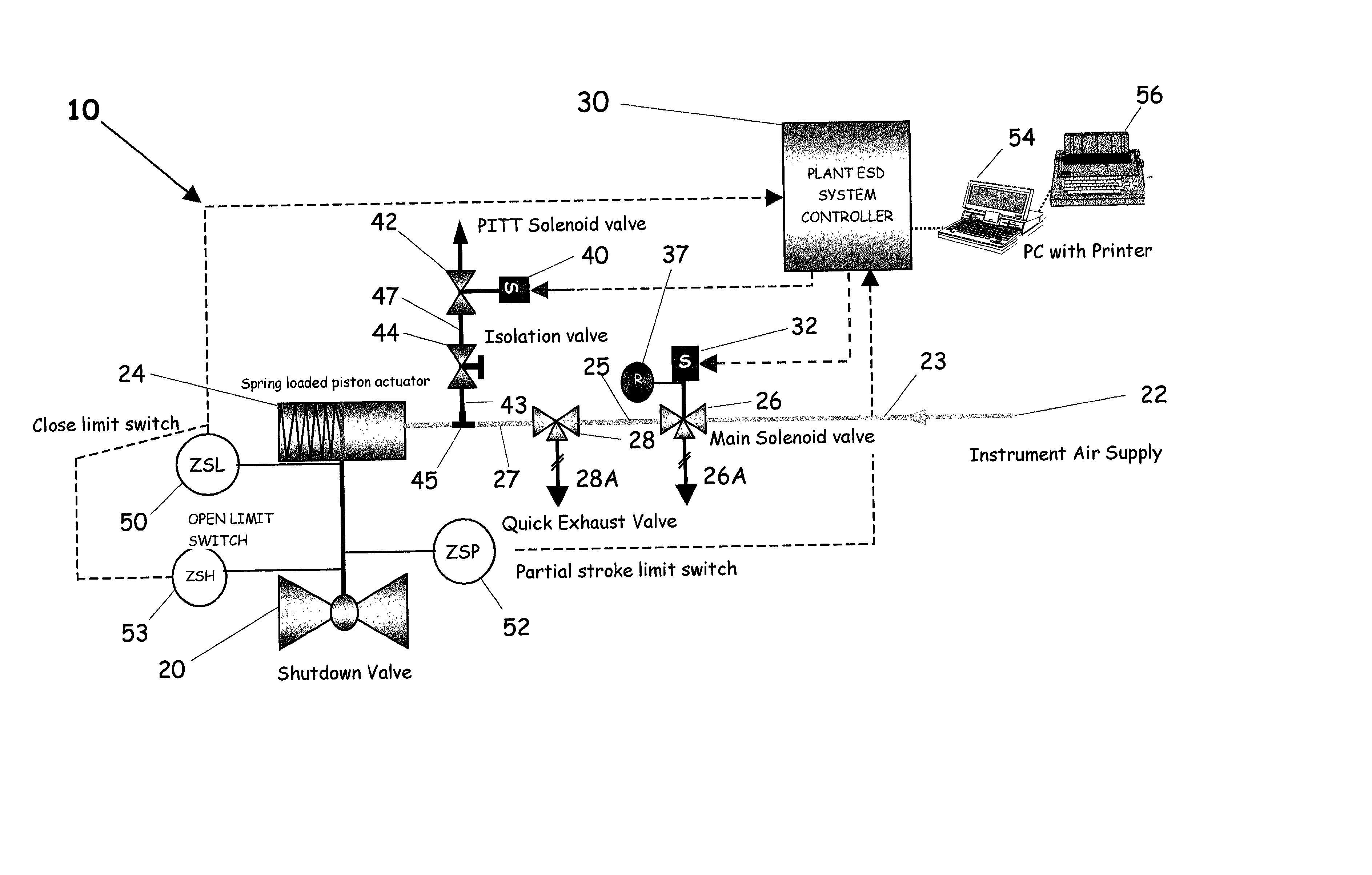
[0007] In addition, the partial stroke testing system in accordance with the present invention will not interfere with a plant trip, i.e. a full shut down due to an emergency condition. Furthermore, if a partial stroke test is being conducted at the time of a plant trip, the partial stroke test will contribute to a more rapid closing of the emergency shut-off valve. Thus, the partial stroking design acts as a backup to the main trip mechanism. Accordingly, such systems should reduce the cost of insurance or risk coverage. In essence, the system partially closes the emergency shut-off valve to a predetermined position to test and confirm its ability to function and to ensure its availability on demand in the event of a plant emergency.

Problems solved by technology

However, there is tendency for such valves to stick or freeze due to corrosion or other reasons, which lead to an unsafe condition.
This problem is exacerbated by economic conditions which have lead to a reduction in the frequency of shutdowns.
However, such systems may not provide for the testing of shut-off valves itself other than stroking the valve.
The problem is that full stroking or completely closing the valve causes an undesirable disruption in the process.

Method used


Image

  • Partial stroke testing system
  • Partial stroke testing system
  • Partial stroke testing system

Examples


Embodiment Construction

[0013] It is well known in the oil, gas and petrochemical industries that emergency shut-off valves are susceptible to a build-up of frictional forces which if undetected can cause failure of the emergency shut-off valve during an out of control process. It is for this reason, that the various regulatory agencies concerned with the safety of such operations, mandate periodic shut-off valve testing and inspection in order to ascertain shut-off valve availability.

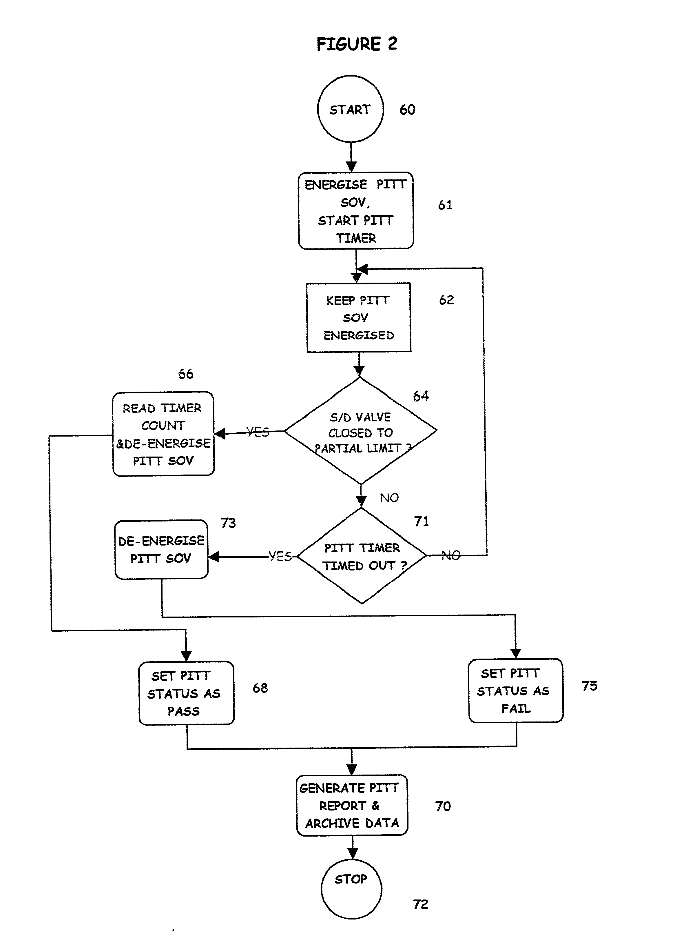
[0014] As disclosed herein, a partial stroke test system tests an emergency shut-off valve on-line, i.e. without shutting down the process, for free movement over a small portion of its full stroke. Therefore, tests can be performed at frequent intervals. By so doing, there is a high probability of ensuring the emergency shut-off valve's operability, which reduce the likelihood of failure of an emergency shut-off valve during extended runs.

[0015] In the oil, gas and petrochemical industries, emergency shut-off valves generall...


PUM

PropertyMeasurementUnit
stroke travel timeaaaaaaaaaa
corrosionaaaaaaaaaa
frequencyaaaaaaaaaa

Abstract

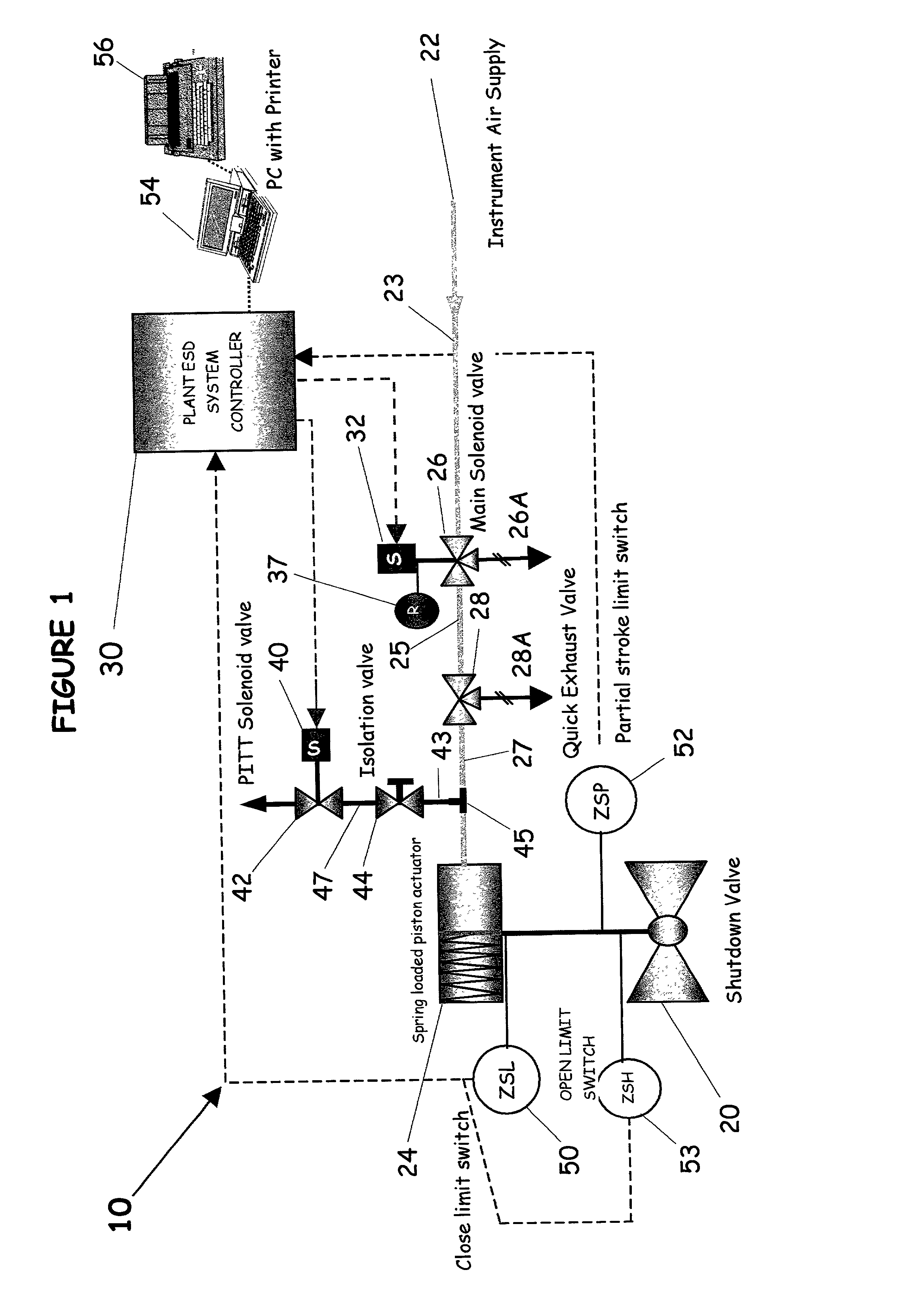
A partial stroke testing system for online testing of emergency shut-off valve, said system is designed for implementation on an emergency shut-off valve with a main solenoid with manual reset, main solenoid valve, quick exhaust valve and a pneumatic actuator connected to a source of pressurized air supply for opening and closing the said emergency shut-off valve and the said shut-off valve normally movable between a fully open and fully closed position. The system also include control means programmed into the plant emergency shutdown system controller for initiating electrical signal for initiating a test and for enhancing the bleed rate from the said pneumatic actuator in the event of a emergency trip signal. Test means for testing the said emergency shut-off valve without fully closing the emergency shut-off valve in response to signal from the said control means is included in the system. The said test means, controlled by the said control means, include a second solenoid and a second solenoid valve for bleeding off pressurized air to thereby move the said emergency shut-off valve from full opened position to partially closed position. Means for limiting the movement of said emergency shut-off valve to a partially closed position because of the bleeding of pressurized air is included in the system. The system also includes an isolation valve for isolating the said test means for maintenance purpose.

Description

[0001] This invention relates to a partial stroke testing system and more particularly to a partial stroke testing system for the online testing of an emergency shut-off valve.BACKGROUND FOR THE INVENTION[0002] In the oil, gas, petroleum and power industries, various conditions may occur that necessitate immediate shut down or tripping of the operations, process or plant In those industries, a majority of the final control element of shutdown systems are implemented with fast acting shut-off valves. In such industries, a majority of the shut-off valves remains open while the process is in a safe and controlled state. Such valves are closed only upon a plant trip rising from an out of control process or during a normal maintenance outage.[0003] In practice, the testing of emergency shut-off valve is normally done during shut down of the process. However, there is tendency for such valves to stick or freeze due to corrosion or other reasons, which lead to an unsafe condition. This pro...

Claims


Application Information

Patent Timeline
Patent Type & Authority Applications(United States)
IPC IPC(8): F16K37/00
CPCF16K37/0083
Inventor ALBUAIJAN, TAREQ NASSER
Owner ALBUAIJAN TAREQ NASSER
Learn More