


Quick Research
Generate reliable direction feasibility study reports for your R&D in just a few steps.

Technical Q&A
Discover and master advanced knowledge NOW. Basics, ideas, possibilities, all at once.

Find Solutions
As an expert in R&D theories, this can generate solutions to your technical problems instantly.

Evaluate Feasibility
Analyze your overall solution with one click, know your potential R&D risks in advance.

Monitor Landscape
Get weekly tech updates, stay abreast of the latest tech innovations and key insights.
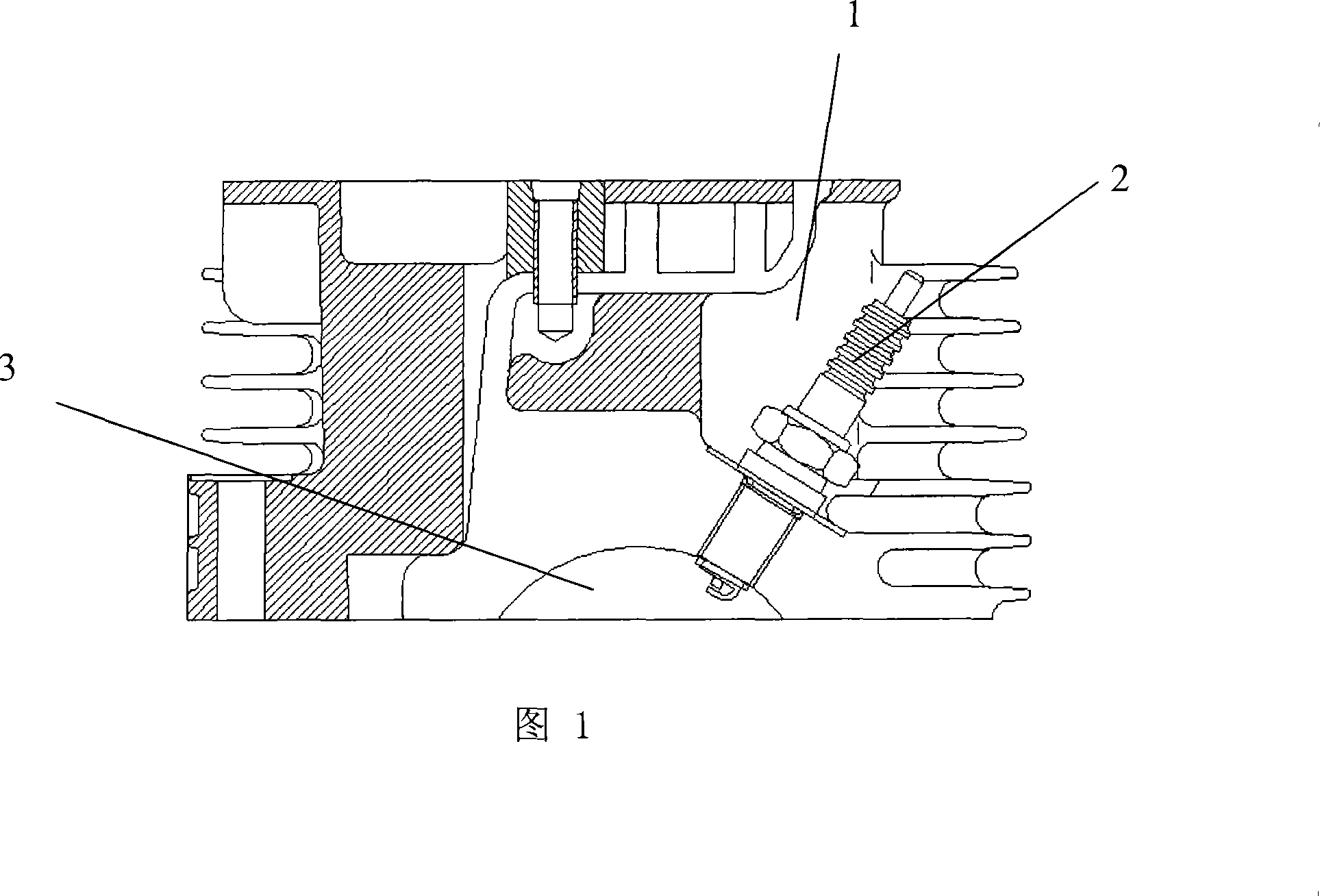
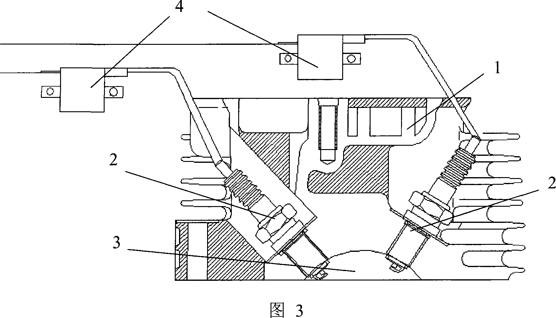
Combustion system of spark-ignition engine
A combustion system, spark ignition technology, applied in the direction of automatic control, automatic control, electrical automatic control, etc., can solve the problems of reducing emissions, rough engine work, and increased combustion cycle changes, so as to increase the flame propagation speed and shorten the flame propagation distance, reducing the effect of burning duration
- Summary
- Abstract
- Description
- Claims
- Application Information
AI Technical Summary
Problems solved by technology
Method used
Image

Examples
Embodiment Construction
[0026] The present invention will be described in detail below with reference to the drawings and examples.
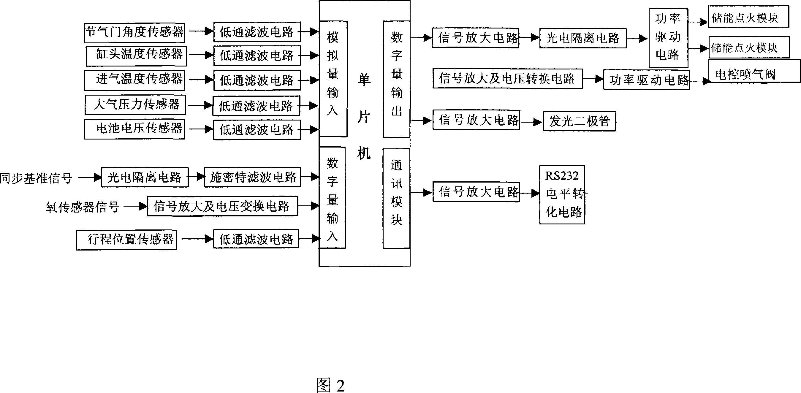
[0027] Fig. 2 is a functional block diagram of the electronic control unit ECU of the spark ignition engine combustion system of the present invention.
[0028] As shown in Figure 2, the synchronous reference signal is the engine speed signal, which passes through the output signal of the engine magneto trigger coil, and is processed into a square wave signal by the photoelectric isolation circuit and Schmidt filter circuit and enters the microcontroller; the engine load signal is the throttle The output signal of the throttle angle sensor of the body component is processed by the low-pass filter circuit and then input to the single-chip microcomputer; or the output signal of the intake air negative pressure sensor is processed by the low-pass filter circuit and then input to the single-chip microcomputer; the intake air and cylinder The signal output by the body tempe...
PUM
 Abstract
Description
Claims
Application Information
 - R&D Engineer
- R&D Manager
- IP Professional
- Industry Leading Data Capabilities
- Powerful AI technology
- Patent DNA Extraction
Browse by: Latest US Patents, China's latest patents, Technical Efficacy Thesaurus, Application Domain, Technology Topic, Popular Technical Reports.
© 2024 PatSnap. All rights reserved.Legal|Privacy policy|Modern Slavery Act Transparency Statement|Sitemap|About US| Contact US: help@patsnap.com