
LCD panel driving circuit and LCD

A liquid crystal display and liquid crystal panel technology, which is applied in the field of liquid crystal displays and liquid crystal panel drive circuits, can solve the problems of low programming reliability and display programming reliability, and achieves the effects of improving programming reliability and reducing rework costs.

Inactive Publication Date: 2008-05-07
INNOCOM TECH SHENZHEN +1
View PDF0 Cites 9 Cited by
  • Summary
  • Abstract
  • Description
  • Claims
  • Application Information

AI Technical Summary

Problems solved by technology

[0009] In order to solve the problem of low programming reliability of the LCD panel driving circuit in the prior art, it is necessary to provide a liquid crystal panel driving circuit with high programming reliability.
[0010] In order to solve the problem of low burning reliability of liquid crystal displays in the prior art, it is also necessary to provide a liquid crystal display with high burning reliability

Method used


Image

  • LCD panel driving circuit and LCD
  • LCD panel driving circuit and LCD
  • LCD panel driving circuit and LCD

Examples


Embodiment Construction

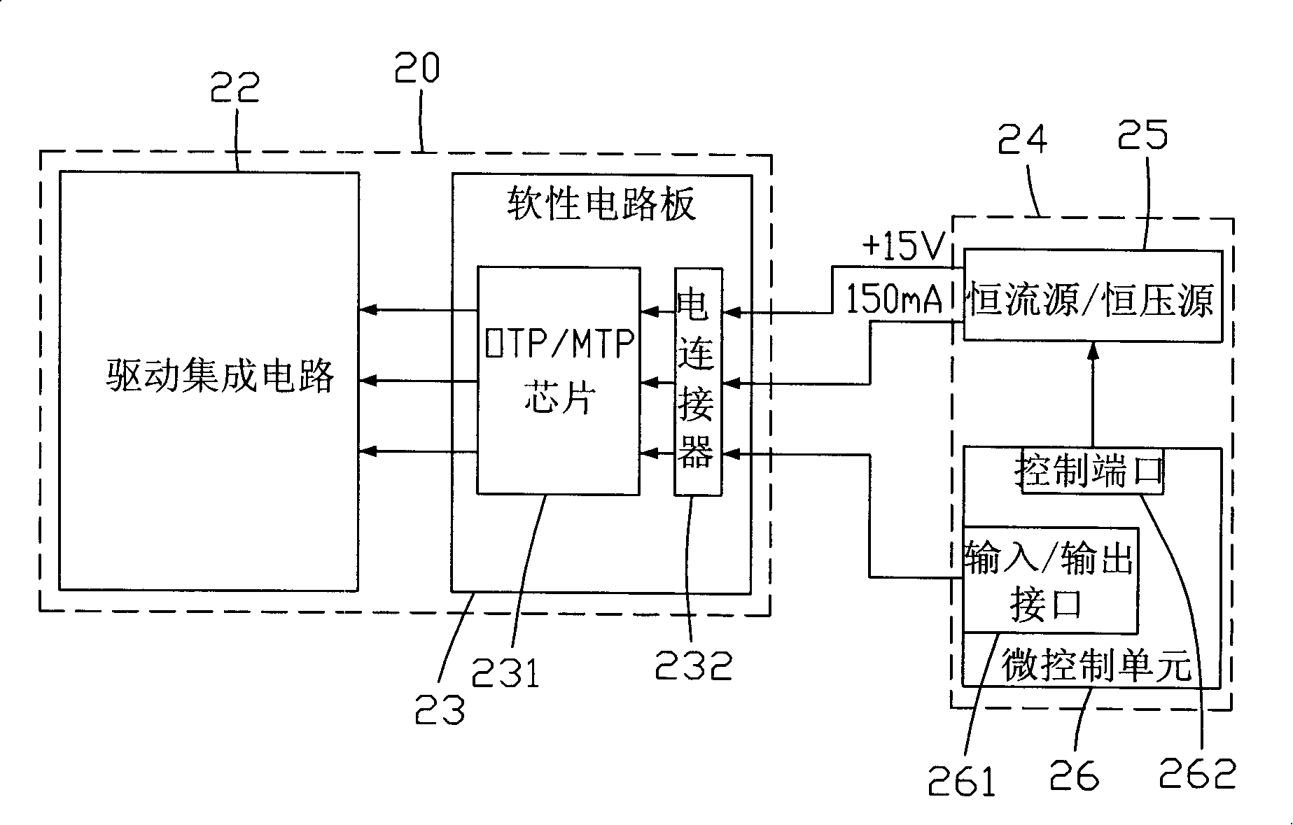
[0017] see figure 2 , is a schematic diagram of the circuit structure for burning in a preferred embodiment of the liquid crystal panel driving circuit of the present invention. The liquid crystal panel driving circuit 20 provides a working voltage and a working signal for a liquid crystal panel (not shown). Before the liquid crystal panel driving circuit 20 is used, it needs to be burned by a burning device 24, so as to write the burning data required for normal operation.

[0018] The liquid crystal panel driving circuit 20 includes a driving integrated circuit 22 and a flexible circuit board 23 . The driving integrated circuit 22 is connected on a substrate of the liquid crystal panel by COG technology. The flexible circuit board 23 is electrically connected to the driving integrated circuit 22 .

[0019] The flexible circuit board 23 includes an OTP / MTP chip 231 and an electrical connector 232 . The programming device 24 writes and solidifies the programming data in t...


PUM


Abstract

The invention relates to a drive circuit of liquid crystal panel and a liquid crystal display. The drive circuit of liquid crystal panel comprises a drive integrated circuit and a flexible circuit board. The drive integrated circuit is used to drive the liquid crystal panel. The circuit board comprises an OTP / MTP (One Time Programmable / Multi Time Programmable) function module; the OTP / MTP function module receives the acquired imprint voltage and the imprint current for imprinting the drive integrated circuit, and stores the imprint data acquired by the drive integrated circuit. The drive integrated circuit reads imprint data from the OTP / MTP function module. The invention has an advantage of high reliability.

Description

technical field [0001] The invention relates to a liquid crystal panel drive circuit and a liquid crystal display using the liquid crystal panel drive circuit. Background technique [0002] Usually, before using the liquid crystal panel driving circuit, a programming device needs to be used to write programming data required for normal operation, such as frame frequency and common electrode driving signal (Common Electrode Driving Signal, VCOM). The programming data is usually stored in an OTP (One Time Programmable) chip or an MTP (Multi Time Programmable) chip of the LCD panel drive circuit. [0003] figure 1 It is a schematic circuit structure diagram of a prior art liquid crystal panel driving circuit for programming. The liquid crystal panel driving circuit 10 provides a working voltage and a working signal for a liquid crystal panel (not shown). The liquid crystal panel driving circuit 10 includes a driving integrated circuit 12 and a flexible circuit board 13 . Th...

Claims


Application Information

Patent Timeline
IPC IPC(8): G02F1/133G09G3/36
Inventor 杜怀
Owner INNOCOM TECH SHENZHEN
Learn More