
Ignition device for internal combustion engine

An ignition device and internal combustion engine technology, applied in the direction of engine ignition, internal combustion piston engines, and other devices, can solve problems such as complex hardware structure, changes, and unstable idling operation

Inactive Publication Date: 2008-04-23
KOKUSAN DENKI CO LTD
View PDF1 Cites 9 Cited by
  • Summary
  • Abstract
  • Description
  • Claims
  • Application Information

AI Technical Summary

Problems solved by technology

However, in this invention, since in addition to the signal generator, it is necessary to provide a singular point detection circuit that detects the zero crossing point or the peak point of the output voltage of the alternator driven by the internal combustion engine as a singular point, there is a hardware limitation. complex questions
[0015] In addition, since the phase of a singular point such as a zero-crossing point or a peak point of the output voltage of the alternator fluctuates due to the output current of the generator during idling, when determining the ignition position during idling based on the output signal of the singular point detection circuit, The ignition position will change during idling, and there is a possibility of unstable idling operation

Method used


Image

  • Ignition device for internal combustion engine
  • Ignition device for internal combustion engine
  • Ignition device for internal combustion engine

Examples


Embodiment Construction

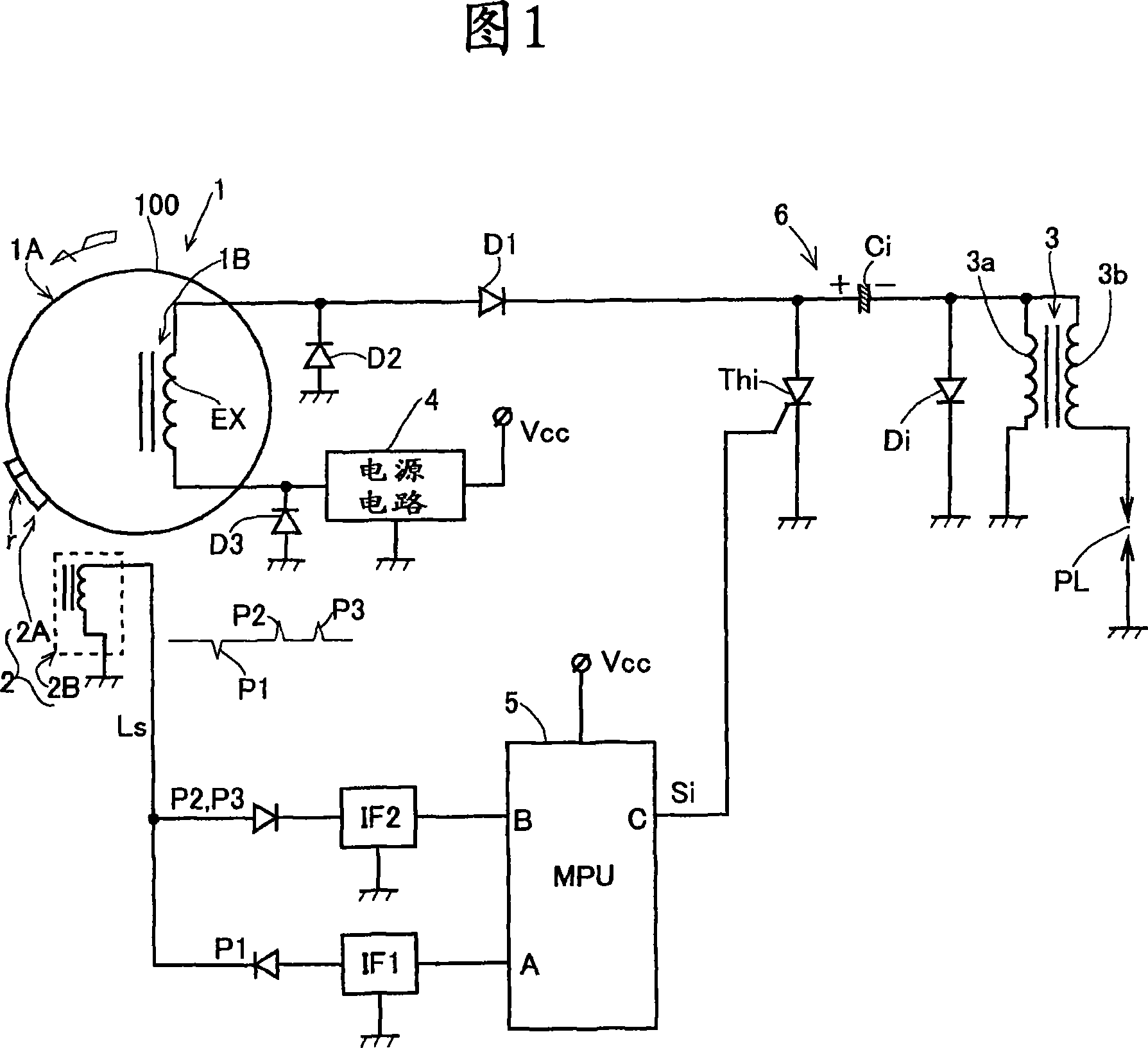
[0036] The present invention will be described in detail below with reference to the accompanying drawings. The present invention can be applied to 2-stroke or 4-stroke internal combustion engines having any number of cylinders, but in the following description it is assumed that the internal combustion engine is a single-cylinder 2-stroke internal combustion engine.

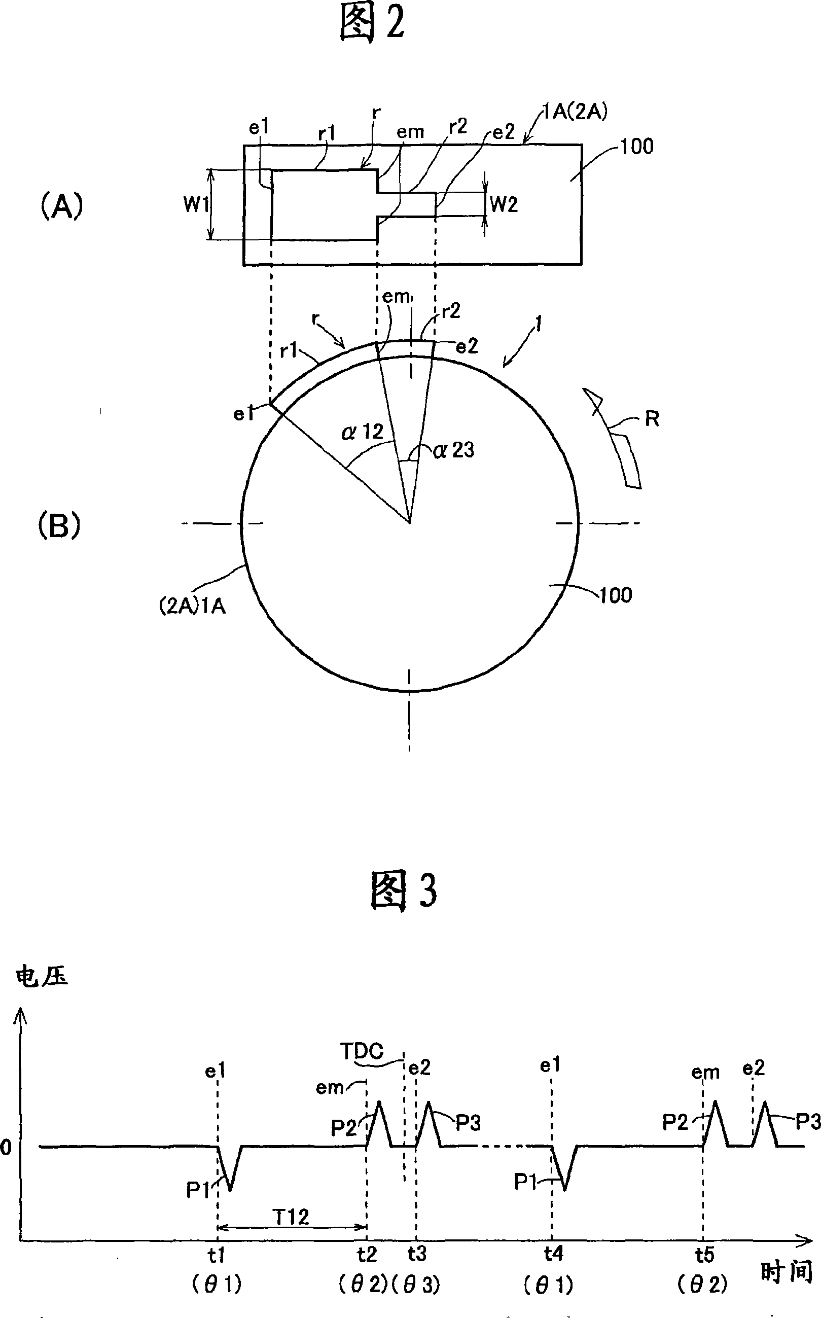
[0037] FIG. 1 shows a configuration example of hardware of an ignition device for an internal combustion engine according to the present invention. In this figure, 1 is a magnet type alternator installed on an internal combustion engine with an outer rotor transformation. The magneto generator 1 is composed of a rotor 1A having a rotor yoke 100 formed in a cup shape, a permanent magnet (not shown) fixed on the inner circumference of a peripheral wall portion of the rotor yoke, and mounted on a crankshaft of an internal combustion engine, and a rotor 1A having a The stator core of the magnetic pole portion facin...


PUM


Abstract

The invention provides an ignition device for an internal combustion engine including an ignition circuit (6) which generates high voltage for ignition and an ignition position control portion (10) for controlling ignition position at the time of providing ignition signal (Si). In the invention, in order to avoid recoil at the time of the internal combustion engine starting, a signal generator (2) is provided that generates a first pulse signal (P1), and a second pulse signal (P2) and a third pulse signal (P3) having a different polarity from the first pulse signal (P1), and the ignition position control portion includes: start time ignition signal providing means (11) for providing an ignition signal to an ignition circuit when the signal generator (2) successively generates the pulse signals having the same polarity at the start of the engine; idling time ignition signal providing means (12) for providing an ignition signal to the ignition circuit in response to the second pulse signal (P2) when first ignition at the start is completed and a rotational speed is an idling rotational speed or less; and normal rotation time ignition signal providing means (13) for arithmetically operating an ignition position and providing an ignition signal to the ignition circuit at a crank angle position that matches the arithmetically operated ignition position when the rotational speed of the internal combustion engine exceeds the idling rotational speed.

Description

technical field [0001] The present invention relates to an ignition device for an internal combustion engine that uses a microprocessor to control the ignition position of the internal combustion engine (the crank angle position of the ignition internal combustion engine). Background technique [0002] An ignition device for an internal combustion engine, as disclosed in JP-A-2001-200776, consists of an ignition circuit that controls the primary current of an ignition coil to induce a high voltage for ignition in a secondary coil of the ignition coil when an ignition signal is given, and an ignition position control unit that controls a crank angle position (ignition position) at which an ignition signal is supplied to the ignition circuit. [0003] In an internal combustion engine, a signal generator is installed to obtain engine rotation information including rotation speed information and rotation angle information. Signal generators usually consist of induction generato...

Claims


Application Information

Patent Timeline
IPC IPC(8): F02P1/00F02P3/08F02P5/15
CPCF02P5/1508F02P5/1558F02D2041/0092F02P1/086F02N2250/04F02P3/0846F02P5/1553F02P1/08F02P5/1506F02D2250/06F02P5/1502Y02T10/46F02P7/0675Y02T10/40
Inventor 佐藤弘康
Owner KOKUSAN DENKI CO LTD
Learn More