Meshing chain stopper

A technology of chain stopper and chain, applied in the direction of chain elements, transmission chains, belts/chains/gears, etc.

Active Publication Date: 2013-09-25
TSUBAKIMOTO CHAIN CO
View PDF6 Cites 4 Cited by
  • Summary
  • Abstract
  • Description
  • Claims
  • Application Information

AI Technical Summary

Problems solved by technology

[0003] exist Figure 13 In the above-described interlocking chain lifting device shown, a slipping out of the chain may occur, wherein the interlocking chain 250 slips out of the chain guide 272 after the end of the interlocking chain 250 passes the sprocket teeth of the drive sprocket 240

Method used


Image

  • Meshing chain stopper
  • Meshing chain stopper
  • Meshing chain stopper

Examples


Embodiment

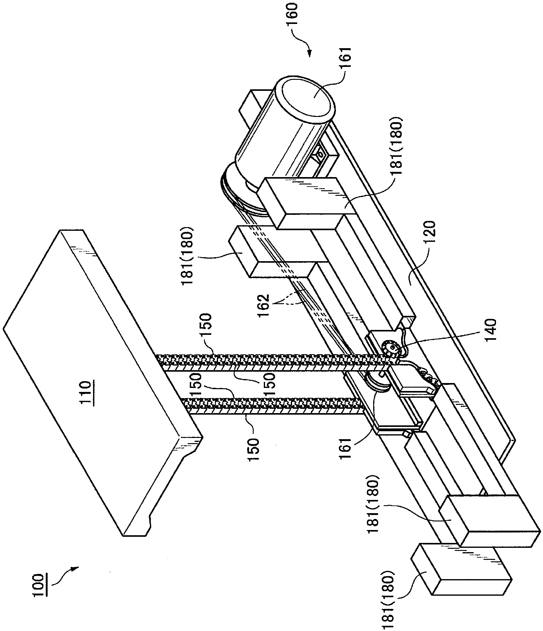
[0051] The following will refer to Figures 1 to 11 An interlocking chain stopper according to one embodiment of the present invention will be described.

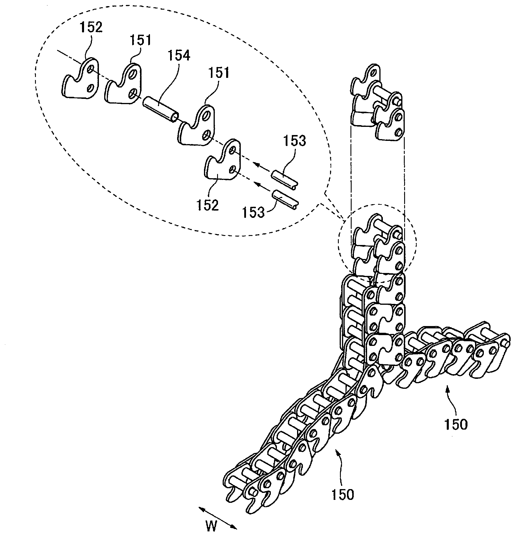
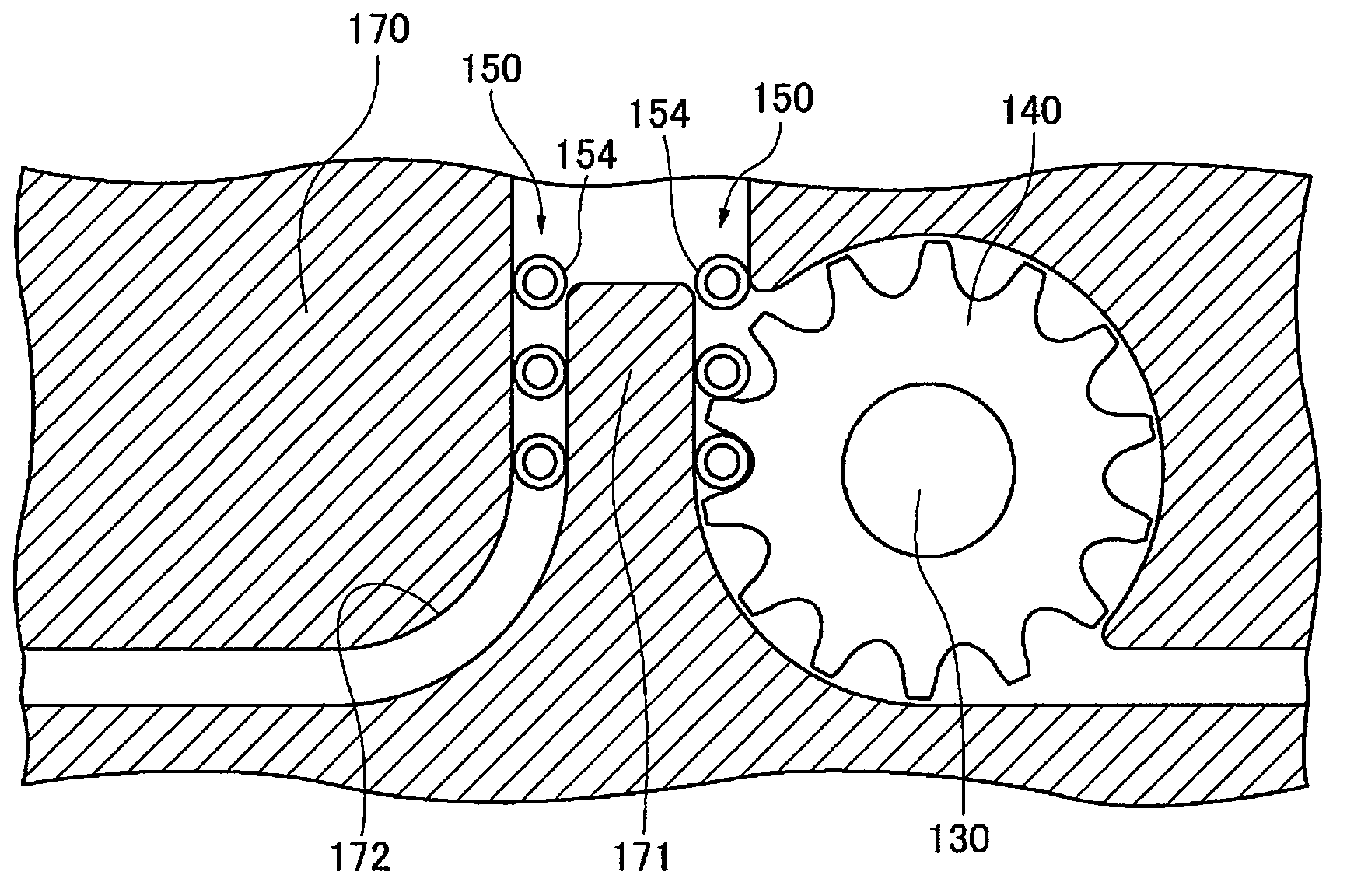
[0052] figure 1 It is a full perspective view of an interlocking chain forward and backward actuating device, which includes an interlocking chain installed with an interlocking chain stopper according to an embodiment of the present invention. figure 2 It is a perspective view showing an exploded state and a disengaged state of the paired interlocking chains. image 3 for close figure 1 An enlarged cross-sectional view of the portion of the drive sprocket and interlocking chain shown. Figure 4 for close figure 1 An enlarged perspective view of the portion of the drive sprocket and interlocking chain shown. Figure 5 It is a perspective view of an installed state of an interlocking chain stopper according to an embodiment of the present invention. Figure 6 for Figure 4 An enlarged view of the contact stop stat...


PUM


Abstract

Chain detachment and chain entry are avoided, and a process for setting the length of a meshing chain is avoided, while the chain feed length can also be freely changed. A meshing chain stopper (190L) comprises a meshing chain stopper attachment part (191) and a contact-stop protrusion (192). The contact-stop protrusion (192) is contact-stopped at a contact-stop point (173A) provided on the periphery of a chain locus (L) when a pair of meshing chains (150, 150) are being driven.

Description

technical field [0001] The invention relates to an interlocking chain stopper for limiting the driving of an interlocking chain. Background technique [0002] In the prior art, there is known a type of actuator in which a driving sprocket coupled with an interlocking chain rotates, thereby driving a pair of interlocking chains to move forward and backward (for example, refer to Patent Document 1). [0003] exist Figure 13 In the above-described interlocking chain lifting device shown, a slipping out of the chain may occur, wherein the interlocking chain 250 slips out of the chain guide 272 after the end of the interlocking chain 250 passes the sprocket teeth of the drive sprocket 240 . Therefore, a control device is provided that outputs position information from a position sensor for detecting the position of the interlocking chain 250 to electrically or mechanically control the rotation speed of the chain driving motor. [0004] prior art literature [0005] patent doc...

Claims


Application Information

Patent Timeline
Patent Type & Authority Applications(China)
IPC IPC(8): F16G13/20
CPCB66F3/06F16G13/06F16G13/20B66F17/00F16G15/00
Inventor 佐治智之
Owner TSUBAKIMOTO CHAIN CO
Why Eureka
Try Eureka