
Storage apparatus comprising read-write cache and cache implementation method

A storage device and read cache technology, which is applied in the field of cache, can solve problems such as distance, limited memory space, and small memory space, and achieve the effects of improving processing efficiency, saving power supply resources, and achieving low cost

Inactive Publication Date: 2008-03-26
NEW H3C TECH CO LTD
View PDF0 Cites 20 Cited by
  • Summary
  • Abstract
  • Description
  • Claims
  • Application Information

AI Technical Summary

Problems solved by technology

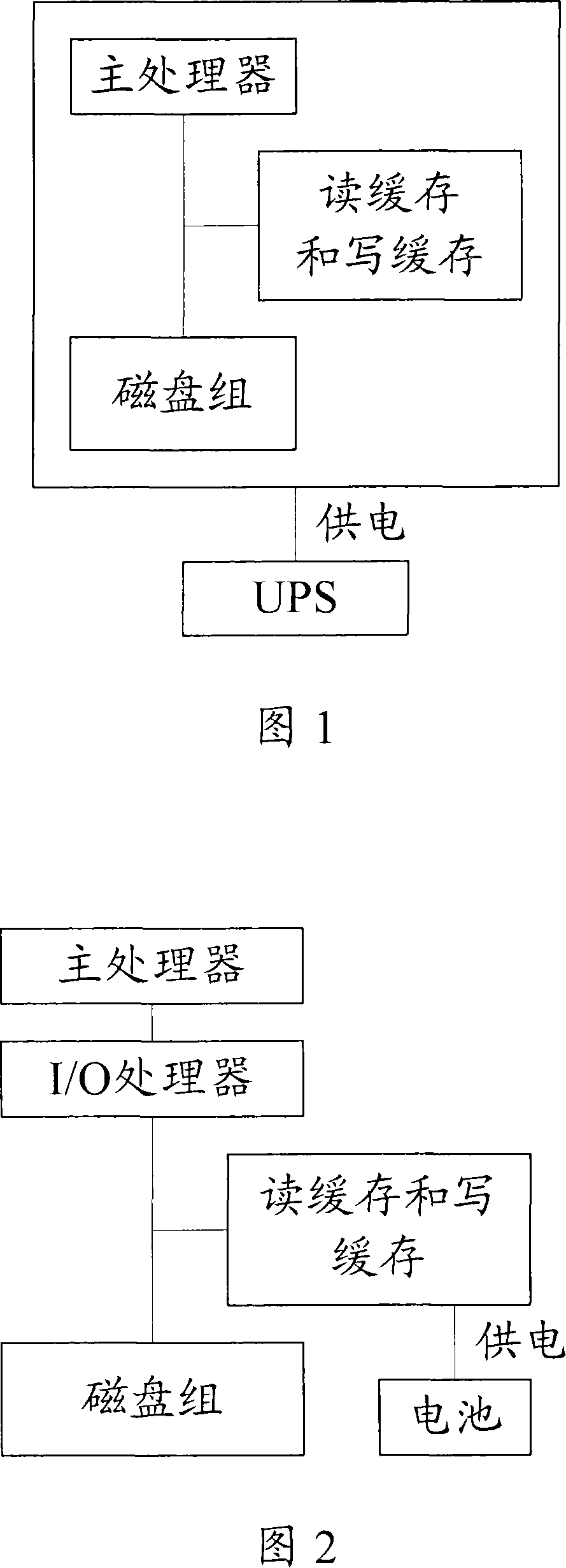
[0015] 1) Both the read cache and the write cache are mounted under the main processor through the I / O processor, that is, they are far away from the main processor, and the processing efficiency after the read and write hits is lower than that of the first solution shown in Figure 1;
[0016] 2) Usually, the memory space that the I / O processor can support (that is, the memory space that is continuously powered by the battery) is relatively limited in size, which is far smaller than the memory space that the main processor can support. The capacity of the read cache and write cache under the / O processor; the read and write efficiency of the read cache and write cache is directly related to its capacity
[0017] 3) In this solution, both the read cache and the write cache are continuously powered, but the read cache does not need continuous power supply, resulting in a waste of resources
[0018] It can be seen that although the cost is reduced in the solution shown in Figure 2 above, since the read cache occupies part of the memory space continuously powered by the battery, the memory space continuously powered by the battery as the write cache is smaller, thus making the memory space continuously powered by the battery smaller. The read and write processing efficiency of the read and write cache is low

Method used


Image

  • Storage apparatus comprising read-write cache and cache implementation method
  • Storage apparatus comprising read-write cache and cache implementation method
  • Storage apparatus comprising read-write cache and cache implementation method

Examples


Embodiment Construction

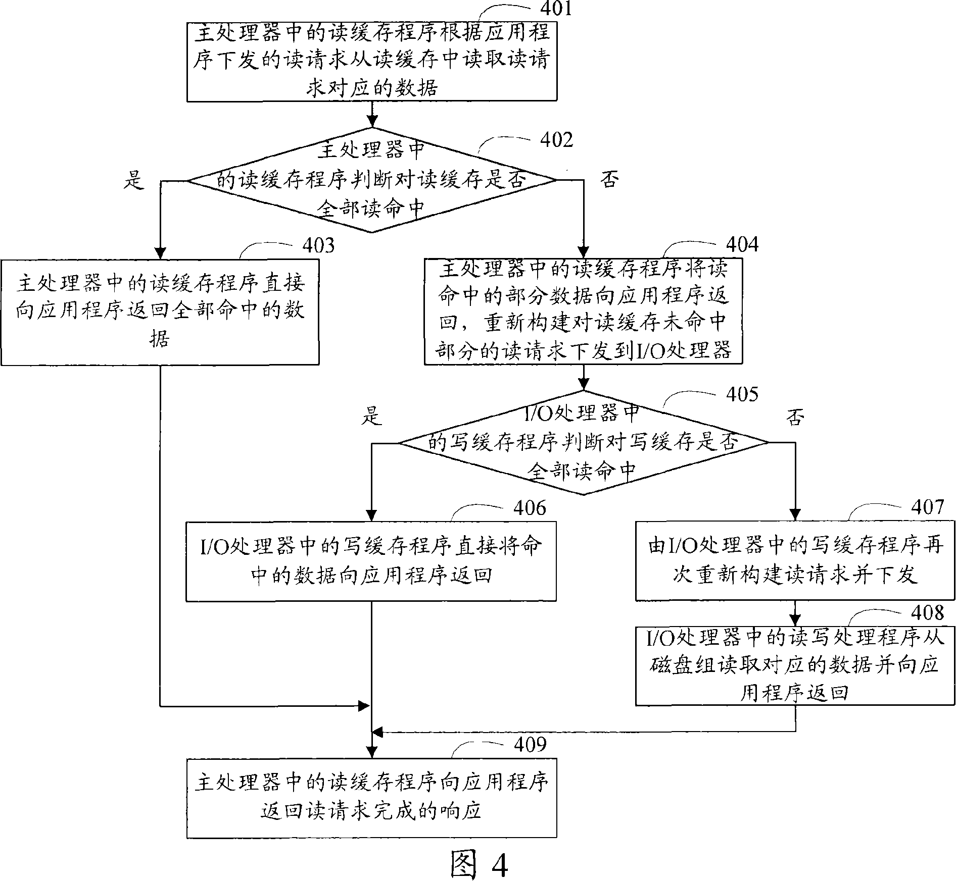
[0073] In order to make the object, technical solution and advantages of the present invention clearer, the present invention will be further described in detail below with reference to the accompanying drawings and examples.

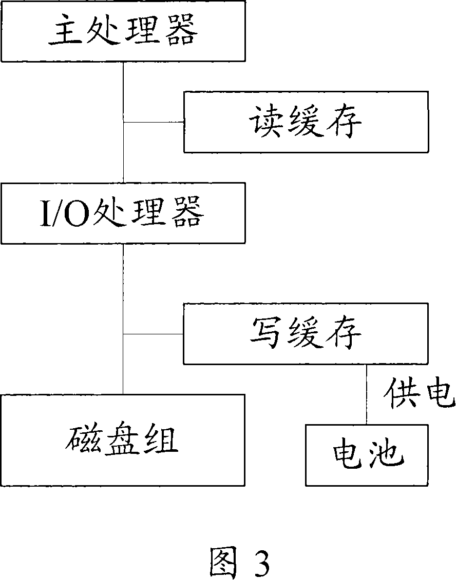
[0074] FIG. 3 is a schematic structural diagram of a storage device in an embodiment of the present invention. As shown in FIG. 3 , the storage device including the read cache and the write cache provided by this embodiment includes: a main processor, an I / O processor, a battery, a read cache, a write cache, and a disk group.

[0075] The difference from the existing solution shown in FIG. 2 is that the read cache and the I / O processor are mounted under the main processor, and the write cache and the disk group are mounted under the I / O processor. The cache and write cache are attached to different processors respectively.

[0076] In this way, the main processor is used to control access to the read cache.

[0077] The I / O processor is used to contro...


PUM


Abstract

This invention discloses one read-write buffer storage device and the method of one storage device's read-write buffer to realize. This invention makes the reading buffer and the writing buffer separate, namely carries on the access control for reading buffer and writing buffer separately by the different processors, namely the reading buffer hangs directly under the main processor, thus enhances the processing efficiency of the main processor to the reading buffer, and the main processor can support the big memory space, thus guarantees the reading buffer have large capacity, then, improves the processing efficiency of the main processor to the reading buffer; The writing buffer hangs under the I / O processor, the I / O processor's necessary battery supply circuit realizes to supply the writing buffer power continually, and the writing buffer doesn't need to share the limited memory space the I / O processor can support with the reading buffer, thus the processing efficiency of the main processor to the writing buffer can be improved as a result of the writing buffer capacity enhancement.

Description

technical field [0001] The invention relates to cache technology, in particular to a storage device including a read-write cache and a method for realizing the read-write cache in the storage device. Background technique [0002] In storage devices, cache is an indispensable storage medium (usually one or more blocks of memory), which can accelerate the access speed of the main processor in the storage device to the disk group, thus greatly improving the overall performance of the storage device. s help. [0003] It should be noted that the physical location and media type of the cache in the storage device mentioned here are different from the internal cache of the CPU of the computer system. [0004] According to the type of access, cache can be divided into read cache and write cache. Wherein, for the storage device, the data in the write cache cannot be lost to avoid the loss of user data; while the data in the read cache is lost, the user data will not be lost. There...

Claims


Application Information

Patent Timeline
IPC IPC(8): G06F3/06G06F13/16G06F12/08
Inventor 李至哲倪小珂
Owner NEW H3C TECH CO LTD
Learn More