Lamp tube driving circuit

A technology for driving circuits and lamp tubes, which is applied to circuits, discharge lamps, electric light sources, etc., and can solve the problems of process complexity and manufacturing cost increase

Inactive Publication Date: 2008-02-13
辜正隆 +1
View PDF1 Cites 4 Cited by
  • Summary
  • Abstract
  • Description
  • Claims
  • Application Information

AI Technical Summary

Problems solved by technology

In fact, inside the drive integrated circuit 70, there is a high-voltage coupling capacitor between the high-voltage output terminal Ho and the low-voltage output terminal Lo, and its withstand voltage must be as high as hundreds of volts. The driver integrated circuit 70 must consider the high-voltage process in terms of semiconductor raw material selection, internal component design, circuit layout, etc., so that the complexity of the process and the manufacturing cost will be relatively increased.

Method used


Image

  • Lamp tube driving circuit
  • Lamp tube driving circuit
  • Lamp tube driving circuit

Examples


Embodiment Construction

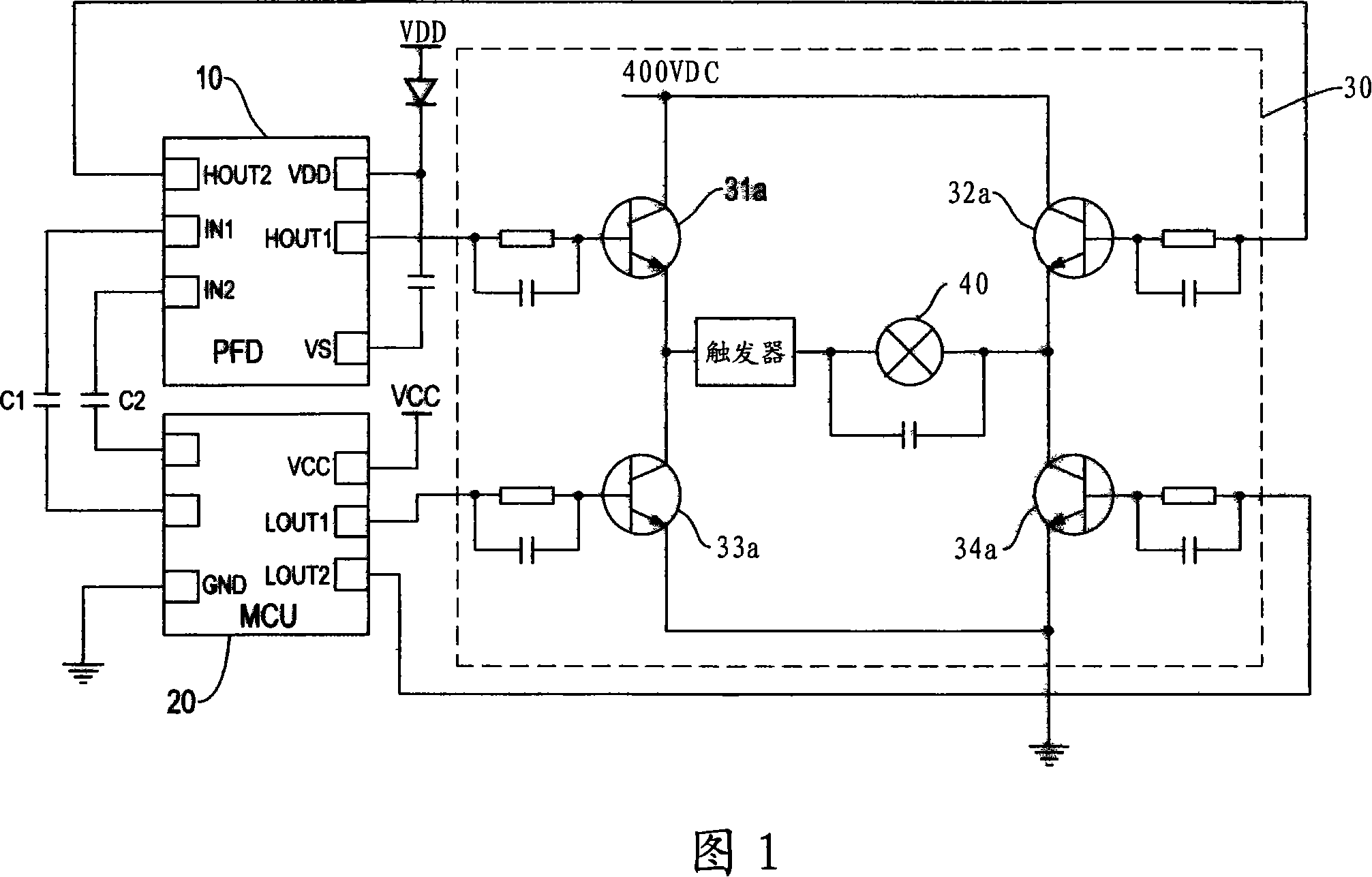
[0052] In order to further explain the technical means and effects of the present invention to achieve the intended purpose of the invention, the specific implementation, structure, characteristics and effects of the lamp drive circuit proposed according to the present invention will be described below in conjunction with the accompanying drawings and preferred embodiments. , as detailed below.

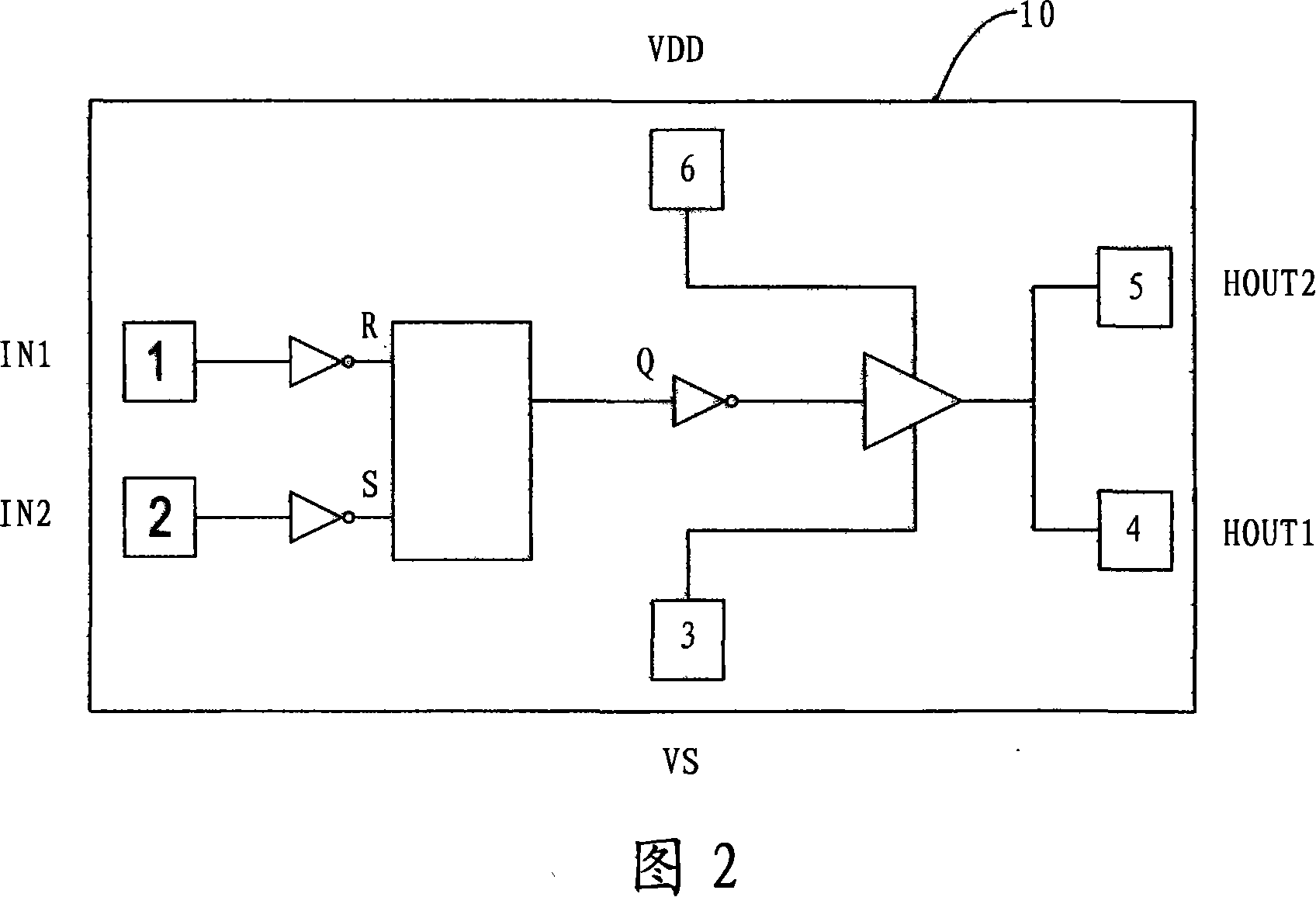
[0053] Please refer to Fig. 1, a floating power driver 10 and a microprocessing unit (MCU) 20 coupled to the floating power driver are used in the lamp driving circuit of the present invention, and a driving unit 30 is jointly controlled by the two. The driving unit 30 is connected to two ends of a lamp tube 40 . The micro-processing unit 20 can also be a general-purpose pulse width modulation control circuit (eg TL494CD), and the micro-processing unit 20 can be designed and developed as an application-specific IC (ASIC) in order to reduce costs.

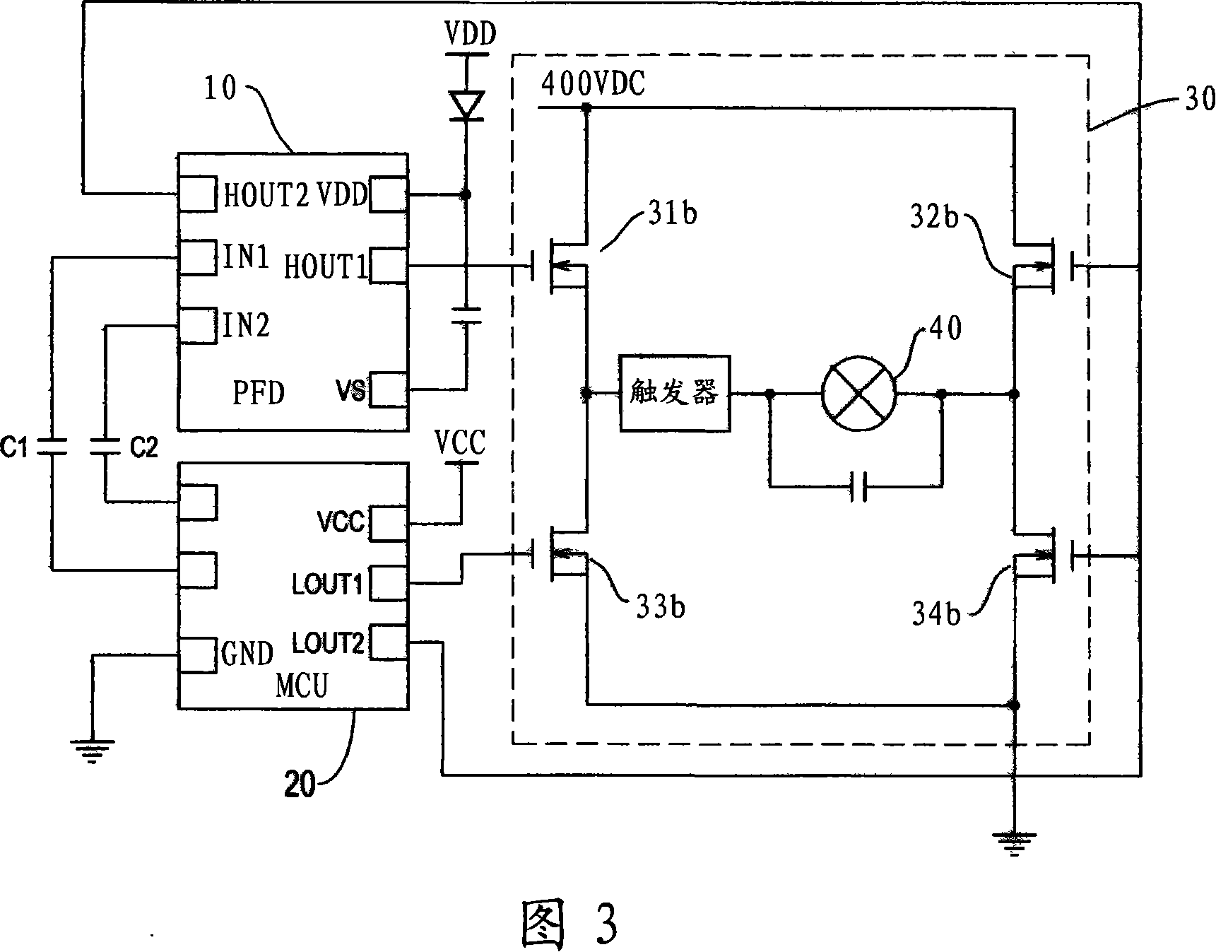
[0054] In this embodiment, the driv...


PUM


Abstract

A lamp driving circuit with a floating power supply driver includes a microcomputing unit (20), a floating power supply driver (10) and a driving unit (30). The microcomputing unit (20) and the floating power supply driver (10) are either two independent integrated circuits or a single integrated circuit and manufactured under a normal voltage. The floating power supply driver (10) is coupled to the microcomputing unit (20) via two independent high-pressure coupling capacitors, instead of sharing the same ground with the microcomputing unit (20). The microcomputing unit (20) and the floating power supply driver (10) provide at least one low-voltage driving pulse output pin and one high-voltage driving pulse output pin to control the driving unit (30) so that a lamp connected to the driving unit (30) can be lit up.

Description

technical field [0001] The invention relates to a lamp tube drive circuit, in particular to a lamp tube drive circuit in which individual integrated circuit components manufactured by normal pressure processes respectively control high and low voltage side drive transistors. Background technique [0002] Please refer to Fig. 7, which is a driving circuit using a current transformer, which can be used to drive a gas discharge lamp 60. The circuit includes a bidirectional trigger switch 61 connected to the DC input terminal, a current transformer 62, two metal oxide The power transistors 63 and 64 are composed of material semiconductor field effect transistors (MOSFET). The primary side winding of the current transformer 62 is connected in series with the lamp tube 60, and its secondary side winding is connected with the aforementioned two power transistors 63, 64. LC circuit, the other end of the capacitor 66 is connected to the primary side winding of the current transforme...

Claims


Application Information

Patent Timeline
Patent Type & Authority Applications(China)
IPC IPC(8): H05B41/36H05B41/282H05B41/14
CPCH02M2001/0006H02M1/08Y02B20/186Y10S315/07H02M7/538H05B41/2828H02M1/0006Y02B20/00
Inventor 辜正隆
Owner 辜正隆
Why Eureka
Try Eureka