
Internal combustion engine providing a phase of scavenging burned gases

A technology for burning exhaust gas and internal combustion engines, which is applied to combustion engines, internal combustion piston engines, mechanical equipment, etc., and can solve problems such as damaging engine operation

Inactive Publication Date: 2008-02-06
INST FR DU PETROLE
View PDF1 Cites 8 Cited by
  • Summary
  • Abstract
  • Description
  • Claims
  • Application Information

AI Technical Summary

Problems solved by technology

[0012] Also, outside of the scavenging phase, offset cams are detrimental to the operation of the engine, especially when filling at high speeds

Method used


Image

  • Internal combustion engine providing a phase of scavenging burned gases

Examples


Embodiment Construction

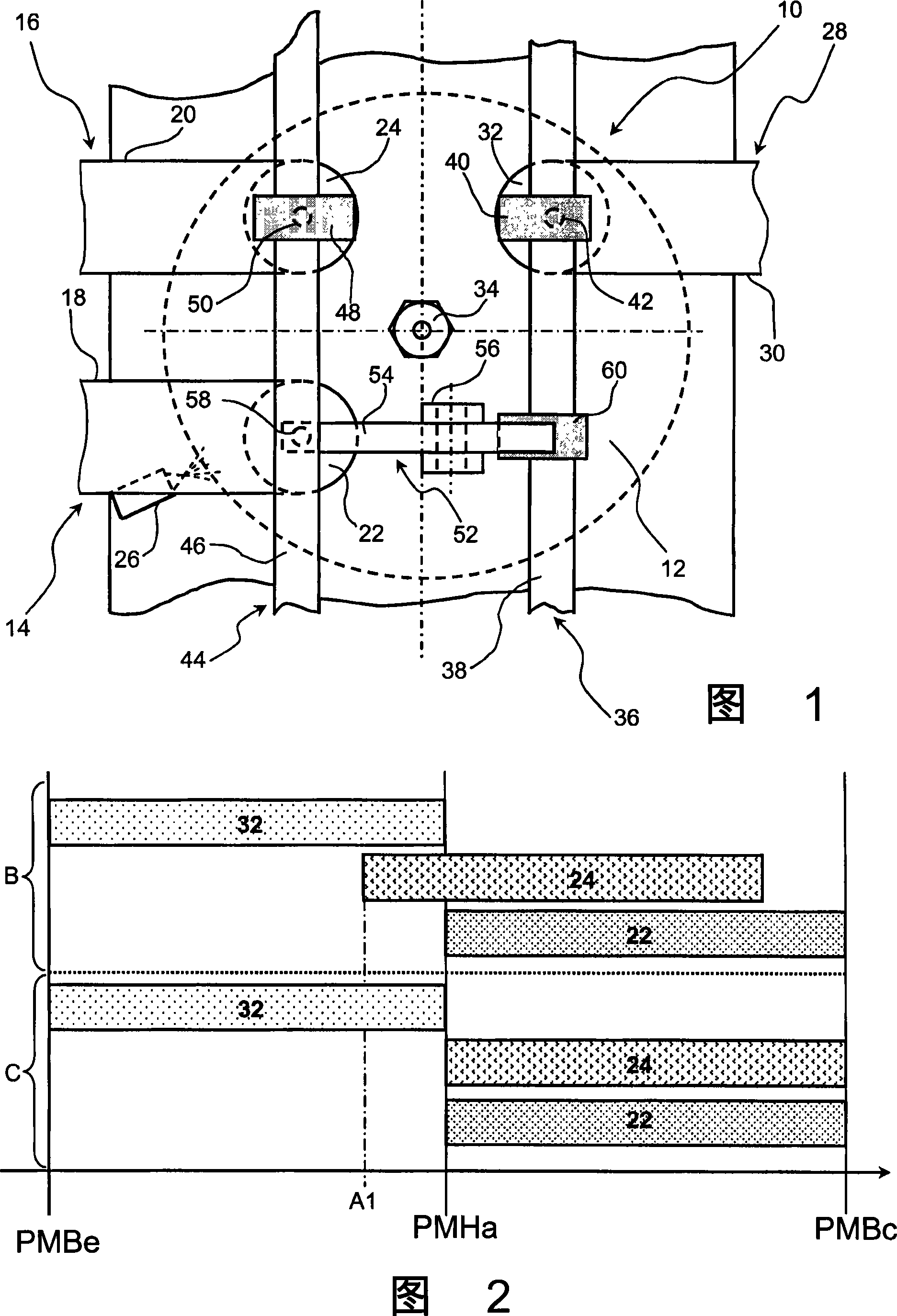
[0027] Figure 1 shows a supercharged internal combustion engine, especially of the indirect fuel injection type, more specifically a spark ignition engine.

[0028] This engine comprises at least one cylinder 10 in which a piston (not shown) reciprocates in a straight line at a first position called top dead center (PMH in the figure) and at a first position called bottom dead center (PMB). ) to another location. The cylinder comprises a combustion chamber 12 in which air or a mixture of charge air and fuel, or a mixture of charge air and fuel to which recirculated exhaust gas (EGR) has been added, is combusted.

[0029] The cylinder 10 includes a charge air (or carbonized air) intake 14 and a charge air (or air) intake 16 , the latter air being non-carbonated air in the example shown.

[0030] These air intake means generally consist of an orifice provided in the cylinder head, the engine usually being equipped with pipes 18, 20 communicating with this orifice and means 22, ...


PUM


Abstract

The engine has a cylinder (10) with carburized and uncarburized air inlet units (14, 16) with carburized and uncarburized air inlet valves (22, 24), respectively. The valve (24) is controlled by opening / closing of an opening by a variable valve timing type controlling unit (44) having a rotating camshaft (46) and a cam (48) for varying a raised status of the valve (24). The valve (22) is controlled by an additional controlling unit having a cam shaft and an activation unit (52) for activating the valve (22) controlled by an controlling unit (36) of a burned gas exhausting unit (28).

Description

technical field [0001] The invention relates to an indirect injection internal combustion engine comprising at least two intake arrangements for carrying out a scavenging phase of residual combustion exhaust gases. More specifically, the present invention relates to, inter alia, a spark ignition supercharged engine. Background technique [0002] It is well known that the power delivered by an internal combustion engine depends on the quantity of air fed into the combustion chamber of the engine, which is itself proportional to the density of this air. [0003] If higher engine power is required, the air volume is increased by compressing the air by means of a booster (turbocharger or driven compressor such as a screw compressor) before it is fed into the combustion chamber. [0004] In order to increase the amount of compressed air admitted into the cylinder, a stage is provided to scavenge the residual combustion exhaust gases present in the combustion chamber. This scave...

Claims


Application Information

Patent Timeline
IPC IPC(8): F02B25/00F02B33/00F02B41/00F02D23/00
CPCY02T10/146F01L1/053F02B29/086F01L1/34Y02T10/18F02B17/00F02D13/0261F01L1/18Y02T10/12
Inventor A·帕高特
Owner INST FR DU PETROLE
Learn More