
Combined insulator

A technology for composite insulators and sheds, which is applied in the high-voltage field, can solve the problems of affecting the safe operation of the power grid, the short life of composite insulators, and the flashover of composite insulators. reliability effect

Inactive Publication Date: 2008-01-30
丁清
View PDF0 Cites 6 Cited by
  • Summary
  • Abstract
  • Description
  • Claims
  • Application Information

AI Technical Summary

Problems solved by technology

The service life of naturally aging composite insulators is more than 30 years. However, in actual operation, due to the accelerated aging of local external insulation materials, some existing composite insulators are seriously aged in only three or five years, and severely aged composite insulators are prone to flashover. Network and fracture accidents have directly affected the safe operation of the power grid. The professional journal "Electric Porcelain Lightning Arrester" sponsored by Xi'an Electric Porcelain Research Institute, No. 4, 2005, "Corrosion Test and Electric Field Calculation Analysis of 500KV Rod Suspension Composite Insulators with Fractured Operation" This article provides examples of line faults caused by severe aging of the outer insulation material of typical composite insulators
Therefore, the problems existing in the existing composite insulators are: composite insulators have short service life and low reliability due to accelerated aging of local external insulation materials

Method used


Image

  • Combined insulator
  • Combined insulator
  • Combined insulator

Examples


Embodiment Construction

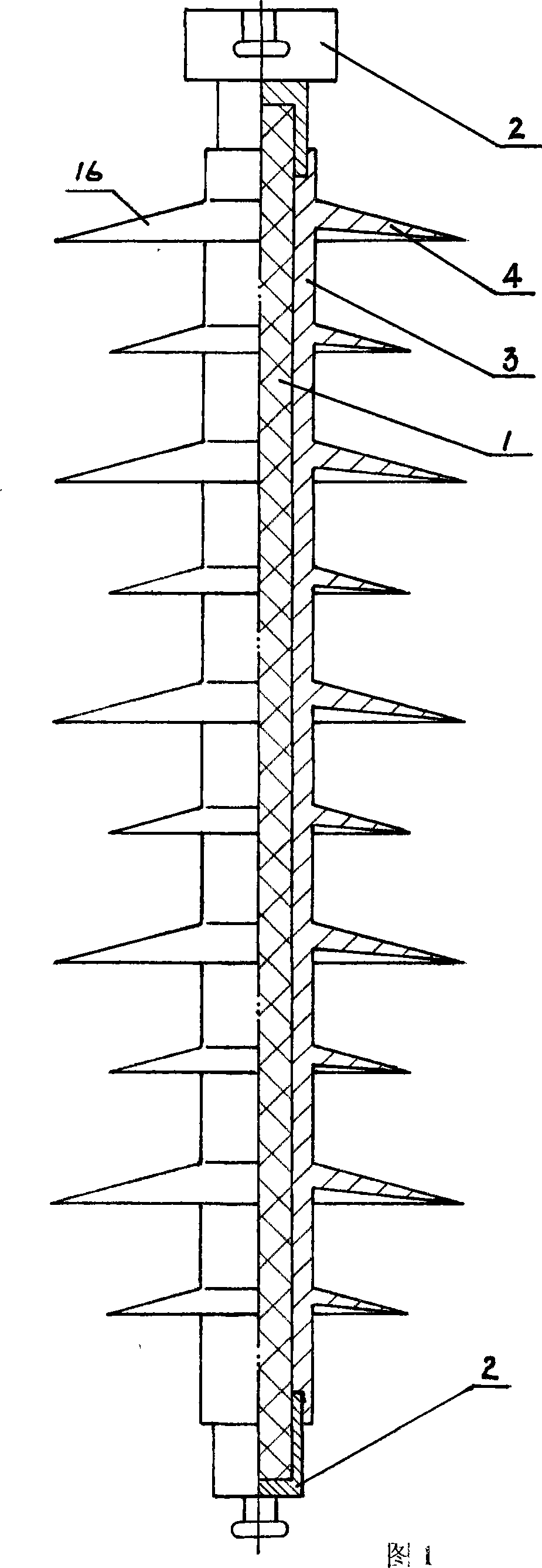
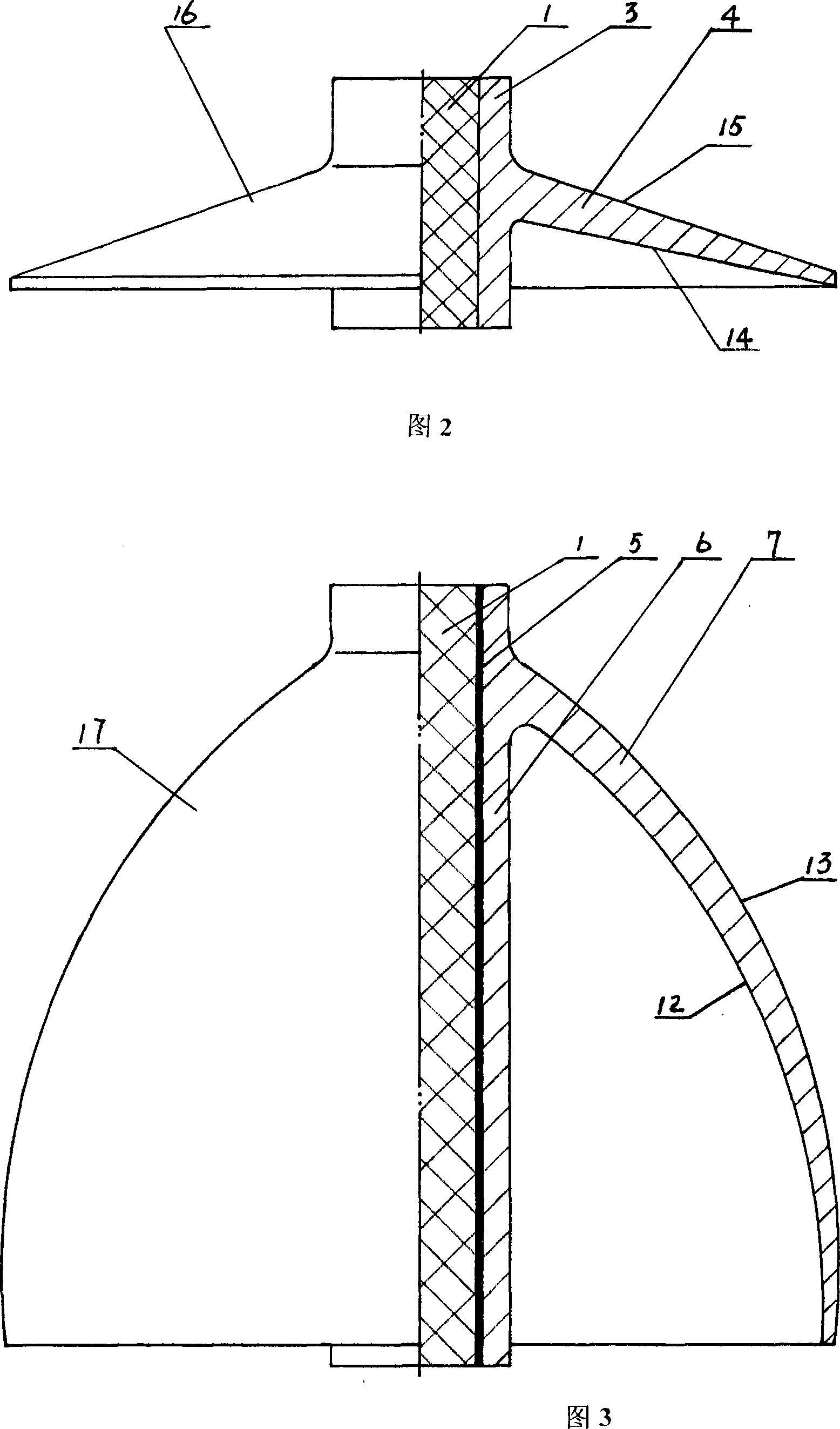
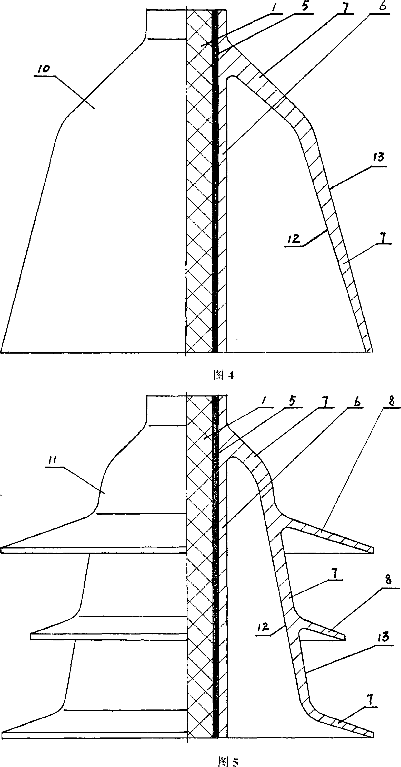
[0021] Fig. 6 is a structural schematic diagram of a composite insulator of the present invention. The upper part of the composite insulator adopts a plurality of existing sheds, and the lower part adopts two arc-shaped "bell jars" as shown in Fig. 3 Umbrella skirts are connected in series, and the center line of the axial half-section of the main shed skirt of the arc-shaped "bell-type" sheath is an arc segment, and the inclination angle of some arc segments is greater than 60°. Cavity depth greater than 45mm. A composite insulator of the present invention shown in Fig. 6 is produced in the following way: 1) use the arc-shaped "bell type" umbrella shed special mold to press and form two silicon rubber materials as shown in Fig. 3 and connect with outer sheath respectively Arc-shaped "bell-type" sheds, and cleaned and inspected; 2) Put the clean and dry mandrel into the existing integral mold for sheds and sheaths, place it on the injection vulcanizing machine, and inject it i...


PUM


Abstract

The invention belongs to a high voltage technical field, in particular relating to a long rod suspension typed compound insulator. The compound insulator consists of a core rod, a connecting hardware fitting, an insulating rubber jacket and a full skirt, which is characterized in that: the compound insulator is provided with at least one 'phosphorizer-typed' full skirt. A top of a main full skirt body of the 'phosphorizer-typed' full skirt is connected with the jacket. The main full skirt body obliquely extends from the top to the bottom to form an inner cavity of 45 mm or more than 45 mm with an open bottom. A part or full skirt of the compound insulator adopts the 'phosphorizer-typed' full skirt, of which an inner surface is not easy to be damped and can inhibit a leaking current on the surface of the compound insulator from increasing in a humid climate environment to improve an anti aging performance and a reliability of the compound insulator.

Description

technical field [0001] The invention belongs to the technical field of high voltage, and in particular relates to a composite insulator installed and used vertically in a high-voltage power transmission and transformation system, in particular to a rod-shaped suspension composite insulator used in a power transmission and transformation line. Background technique [0002] Composite insulators are composed of mandrels, connecting fittings at both ends of mandrels, insulating sheaths and sheds covered by mandrels. Emerging composite insulators are widely used in power systems due to their light weight, high strength, good electrical performance, and easy maintenance. . The shed types of the existing composite insulators all belong to the "upper and lower structure". The top is connected to the sheath and extends outward at an inclination angle of less than 30°. The outer insulating surface of the shed is composed of an upper surface and a lower surface. The inclination angle ...

Claims


Application Information

Patent Timeline
IPC IPC(8): H01B17/04H01B17/42
Inventor 丁清
Owner 丁清
Learn More