
Fiber reinforcement resin radical compound material drive axle

A technology of fiber-reinforced resin and composite materials, applied in shafts, shafts and bearings, mechanical equipment, etc., can solve problems such as poor salt spray resistance, poor impact resistance, and poor high temperature resistance

Inactive Publication Date: 2008-01-30
HARBIN FRP INST
View PDF0 Cites 11 Cited by
  • Summary
  • Abstract
  • Description
  • Claims
  • Application Information

AI Technical Summary

Problems solved by technology

[0003] In order to solve the problems of poor high temperature resistance, poor wear resistance, poor heat and humidity resistance, poor salt spray resistance, and poor impact resistance existing in the existing composite material drive shaft, the present invention further provides a fiber-reinforced resin-based composite material drive shaft

Method used


Image

  • Fiber reinforcement resin radical compound material drive axle

Examples


specific Embodiment approach 1

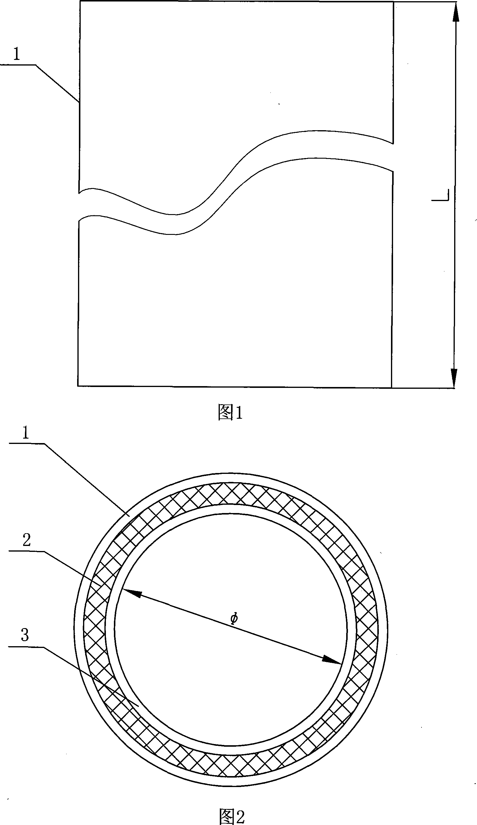
[0007] Specific embodiment 1: As shown in Figure 1 and Figure 2, the fiber reinforced resin matrix composite transmission shaft of this embodiment is composed of a structural layer 2, a surface layer 1, and an inner lining layer 3, and the structural layer is made of fiber reinforced resin The hollow shaft body 2 of composite material, the inner lining layer 3 and the surface layer 1 are respectively adhered to the inner and outer surfaces of the hollow shaft body 2 of fiber reinforced resin matrix composite material.

specific Embodiment approach 2

[0008] Embodiment 2: The hollow shaft body 2 of fiber-reinforced resin-based composite material described in this embodiment is made of one of glass fiber, carbon fiber or aramid fiber. With such materials, the strength and rigidity of the present invention can be enhanced and the overall weight can be lightened. Other compositions and connections are the same as in the first embodiment.

specific Embodiment approach 3

[0009] Embodiment 3: The fiber-reinforced resin-based composite material hollow shaft body 2 described in this embodiment is composed of any two materials of glass fiber, carbon fiber, and aramid fiber in any ratio or a combination of the above three materials in any ratio . With such materials, the strength and rigidity of the present invention can be enhanced and the cost can be reduced. Other compositions and connections are the same as in the first embodiment.


PUM

PropertyMeasurementUnit
Inner diameter φaaaaaaaaaa
Lengthaaaaaaaaaa

Abstract

A fiber enforced resin based compound material transmission shaft pertains to a compound material transmission shaft, and is mainly applied to the transmission systems and precision instruments of such fields as mechanics industry, aviation industry and aerospace industry. The invention solves the problems of the existing compound material transmission shaft, such as poor high temperature resistance, abrasion resistance, humidity resistance, salt spray resistance, and impact resistance, etc. The invention comprises a structure layer, a surface layer (1), and a lining layer (3); the structure layer is a hollow shaft body (2) made of fiber enforced resin based compound material, the lining layer (3) and the surface layer (1) are respectively stuck on the inner surface and the outer surface of the hollow shaft body (2) made of fiber enforced resin based compound material. The invention has the advantages of high temperature resistance, abrasion resistance, corrosion resistance, comparatively strength and hardness, humidity resistance, salt spray resistance, and impact resistance, etc.

Description

technical field [0001] The invention relates to a composite material transmission shaft, which is mainly used in transmission systems and precision instruments in the fields of machinery, aviation, aerospace and the like. Background technique [0002] The composite drive shaft is a structural part used to transmit dynamic loads such as torque. It is widely used because of its high specific strength, high specific stiffness, excellent vibration damping, fatigue resistance, and corrosion resistance. However, the prior art does not provide a fiber-reinforced resin-based composite transmission shaft, and the composite transmission shaft in the current technology only has a structural layer, without an inner lining layer and an outer layer, and has poor high temperature resistance, poor wear resistance, and heat and humidity resistance. Poor, poor salt spray resistance, poor impact resistance. Contents of the invention [0003] In order to solve the problems of poor high tempe...

Claims


Application Information

Patent Timeline
IPC IPC(8): F16C3/02
Inventor 林再文王维王明寅陈辉石建军郭淑齐王海芳刘芳芳
Owner HARBIN FRP INST
Learn More