
Two-stage series reactor for synthesis of natural gas hydrates

A series reactor, natural gas technology, applied in gas fuel, petroleum industry, fuel and other directions, can solve the problems of hydrate ice blockage and difficulty in timely drainage of spray reactors.

Inactive Publication Date: 2008-01-30
HARBIN INST OF TECH
View PDF0 Cites 13 Cited by
  • Summary
  • Abstract
  • Description
  • Claims
  • Application Information

AI Technical Summary

Problems solved by technology

[0006] The purpose of the present invention is to provide a two-stage series reactor for natural gas hydrate synthesis, to overcome the existing bubbling reactor which is easy to cause hydrate ice blockage on the orifice plate and the spray reactor which is difficult to discharge hydrate in time heat of reaction defect

Method used


Image

  • Two-stage series reactor for synthesis of natural gas hydrates
  • Two-stage series reactor for synthesis of natural gas hydrates

Examples


specific Embodiment approach 1

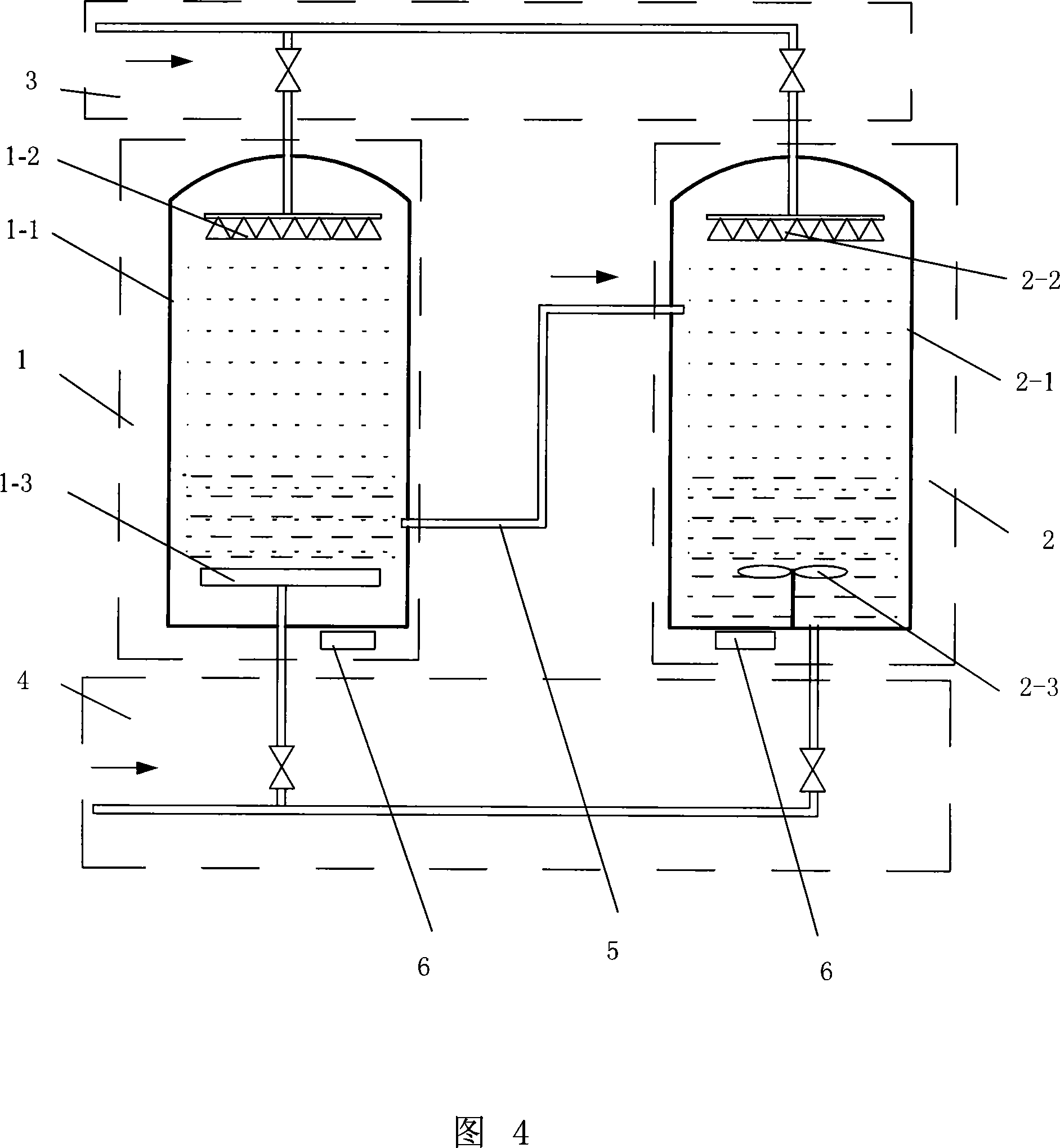
[0009] Specific Embodiment 1: The present embodiment will be specifically described below with reference to FIG. 4 . This embodiment is composed of No. 1 reactor 1, No. 2 reactor 2, water inlet pipe 3, natural gas inlet pipe 4 and delivery pipeline 5. No. 1 reactor 1 is composed of No. 1 kettle body 1-1 and No. 1 spraying device. 1-2 and orifice device 1-3, the No. 2 reactor 2 is composed of the No. 2 kettle body 2-1, the No. It is arranged on the upper top of the inner cavity of the No. 1 kettle body 1-1 and communicates with the water inlet pipe 3. The orifice device 1-3 is arranged at the bottom of the inner cavity of the No. 1 kettle body 1-1 and communicated with the natural gas inlet pipe 4. The No. 2 spraying device 2-2 is arranged on the upper top of the No. 2 still body 2-1 inner cavity and communicates with the water inlet pipe 3, and the stirring device 2-3 is arranged on the bottom of the No. 2 still body 2-1 inner cavity. The bottom of the No. 2 kettle body 2-1 i...

specific Embodiment approach 2

[0010] Specific Embodiment 2: The present embodiment will be specifically described below with reference to FIG. 4 . The difference between this embodiment and Embodiment 1 is that ultrasonic generators 6 are provided at the bottom of No. 1 kettle body 1-1 and the bottom of No. 2 kettle body 2-1. The action of ultrasonic waves can increase the gas storage density of hydrates and accelerate the synthesis speed of hydrates.


PUM


Abstract

The invention relates to a double-stage and serial connection reactor synthesized by natural gas and hydrate relating to a synthesized reactor of natural gas and hydrate. The invention overcomes the defectiveness of the existing reactors of bubbling type that the hydrate is easily iced and blocked on the surface of an orifice plate and the defectiveness of the existing reactor of spraying type that the hydrate heat of reaction is difficult to be drained away. The double-stage and serial connection reactor consists of a No.1 reactor, a No.2 reactor, a water inlet pipe, a natural gas inlet pipe and a transfusion pipe. The No.1 reactor comprises a No. 1 autoclave body, a No. 1 spray device and an orifice plate device, with the No.1 spray device being arranged at the top of the inner chamber of the No.1 autoclave body and communicated with the water inlet pipe and the orifice plate being arranged at the bottom of the inner chamber of the No.1 autoclave body and communicated with the natural gas inlet pipe; the No.2 reactor comprises a No.2 autoclave body, a No.2 spray device and a stirring device, with the No.2 spray device being arranged at the top of the inner chamber of the No.2 autoclave body and communicated with the water inlet pipe and the stirring device being arranged at the bottom of the inner chamber of the No.2 autoclave body and the bottom of the No.2 autoclave body being communicated with the natural gas inlet pipe. The side wall of the No.1 autoclave body is communicated with that of the No.2 autoclave body.

Description

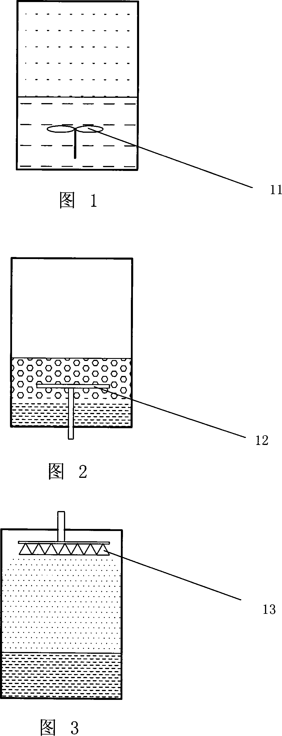
technical field [0001] The invention relates to a synthesis reactor of natural gas hydrate. Background technique [0002] The reactors used for hydrate synthesis in the world can be roughly divided into the following three types: [0003] ①Stirred reactor (see Figure 1): When in use, first fill the reactor with water, the gas enters through the bottom of the reactor, and the gas and water are fully mixed under the action of the stirrer to form natural gas hydrate. Heater, to take away the latent heat released by the generated natural gas hydrate and the heat generated by the rotating parts such as the circulation pump and the stirrer in the reactor in time. However, this simple paddle-shaped stirring reactor has no obvious effect on increasing the gas-liquid interface contact area of ​​hydrate synthesis, and is not suitable for industrial application. [0004] ② Bubble reactor (see Figure 2): High-pressure gas is used to pass through the orifice plate to generate bubbles, ...

Claims


Application Information

Patent Timeline
IPC IPC(8): C10L3/10
Inventor 焦文玲宋汉成赵林波
Owner HARBIN INST OF TECH
Learn More