
Active loop heat sink device with atomizer

A heat-dissipating device and active technology, applied in the field of heat-dissipation technology, can solve the problems of non-compliance with product miniaturization, increase the overall volume, etc., and achieve the effects of improving performance, reducing volume, and improving heat dissipation performance

Inactive Publication Date: 2007-12-19
IND TECH RES INST
View PDF6 Cites 7 Cited by
  • Summary
  • Abstract
  • Description
  • Claims
  • Application Information

AI Technical Summary

Problems solved by technology

[0011] However, when using this spray-cooled droplet cooling device, an external pump must be added to push the droplets out of the micro-spray holes, which will increase the overall volume and do not meet the requirements of product miniaturization

Method used


Image

  • Active loop heat sink device with atomizer
  • Active loop heat sink device with atomizer
  • Active loop heat sink device with atomizer

Examples


Embodiment 1

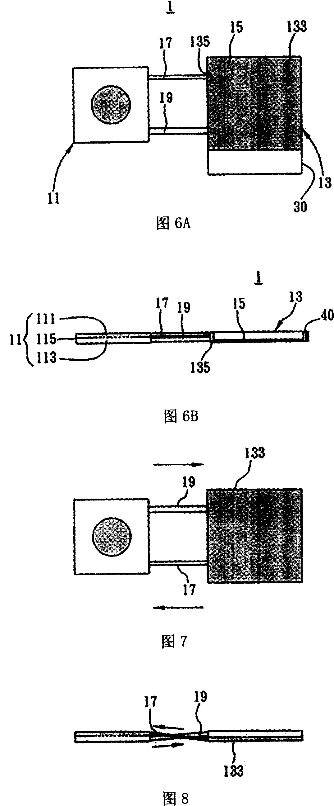
[0033] 3 to 6B are drawings drawn according to Embodiment 1 of the active loop heat sink with atomizer of the present invention.

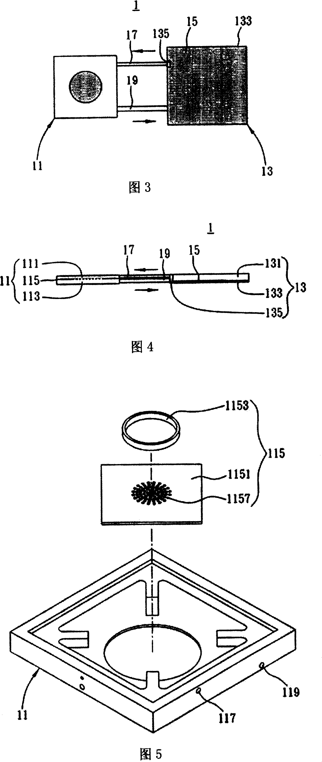
[0034]Fig. 3 is a schematic diagram of the active loop type cooling device with atomizer of the present invention, as shown in the figure, the active loop type cooling device 1 with atomizer is applied in heat source and heat sink (not shown) The heat conduction between the active loop type cooling device 1 with the atomizer includes an evaporation cavity 11, a condensation cavity 13 connected to the evaporation cavity 11, and a flow between the evaporation cavity 11 and the condensation cavity 13 Between the working fluid 15. Meanwhile, in this embodiment, the first channel 17 and the second channel 19 connected between the evaporation cavity 11 and the condensation cavity 13 are provided. In addition, in this embodiment, the evaporation chamber 11 and the condensation chamber 13 communicate with the first passage 17 and the second passage 19, bu...

Embodiment 2

[0048] Figure 7 and Figure 8 are drawings drawn according to Embodiment 2 of the active loop type cooling device with atomizer of the present invention, wherein the same or similar components as those of Embodiment 1 above are denoted by the same or similar component symbols , and omitted the detailed description to make the explanation of this case clearer and easier to understand.

[0049] The biggest difference between this embodiment and embodiment 1 is that the first channel and the second channel of embodiment 1 are arranged in parallel, and the first channel and the second channel of embodiment 2 are arranged alternately.

[0050] As shown in FIG. 7 and FIG. 8 , the first channel 17 and the second channel 19 are alternately arranged, and the first channel 17 is directly connected to the capillary structure 133 , and the capillary structure 135 provided in the first embodiment can be omitted.

[0051] To sum up, in the active loop cooling device with an atomizer of the p...


PUM


Abstract

This invention discloses an active loop radiation device with an atomizer including: an evaporation cavity with a first container, a second container under the first room and an atomizer isolating the two containers, a condensation cavity with a third container connected to the second container and a capillary structure set at one side of the third one and connected to the first container and working fluid filled in the active loop radiation device, which can increase radiation efficiency and reduce heat impedance.

Description

technical field [0001] The invention relates to a heat dissipation technology, in particular to a loop type heat dissipation device of an active cooling technology. Background technique [0002] With the continuous development of the electronic information industry, today's requirements for electronic products include multi-function, fast computing and miniaturization. Therefore, while continuously improving the performance of the internal devices of electronic products, the power consumption of electronic products is also getting higher and higher. LED Array) and multi-chip module package structure (Multi-Chip Module, MCM) and other devices generate heat flux (Heat flux) also increased exponentially. Therefore, how to quickly dissipate heat in the narrow space inside electronic products is the focus of attention. [0003] Taking the CPU device as an example, the existing heat dissipation design generally includes: a heat dissipation device with a vapor chamber, a heat pip...

Claims


Application Information

Patent Timeline
Patent Type & Authority Applications(China)
IPC IPC(8): H05K7/20H01L23/473G12B15/02
CPCH01L23/427F28F2250/08H01L2924/3011F28F13/00H01L2924/0002F28D15/0266H01L23/4735F28D15/043Y10S165/908H01L2924/00
Inventor 吴世国简国祥杨进成黄启明
Owner IND TECH RES INST
Learn More