
Vehicle speed reduction brake light load oil saving device

An automobile and fuel supply technology, which is applied in fuel injection control, engine control, machine/engine, etc., can solve the problems of energy waste and increase the emission of tail gas pollution, so as to reduce exhaust pollution, promote secondary combustion, and save waste. The effect of power supply efficiency

Inactive Publication Date: 2007-12-19
张昌盛
View PDF0 Cites 3 Cited by
  • Summary
  • Abstract
  • Description
  • Claims
  • Application Information

AI Technical Summary

Problems solved by technology

[0004] These two kinds of unnecessary oil supply not only cause waste of energy, but also increase the emission of exhaust pollution

Method used


Image

  • Vehicle speed reduction brake light load oil saving device
  • Vehicle speed reduction brake light load oil saving device
  • Vehicle speed reduction brake light load oil saving device

Examples


Embodiment Construction

[0030] The present invention will be further described below in conjunction with accompanying drawing:

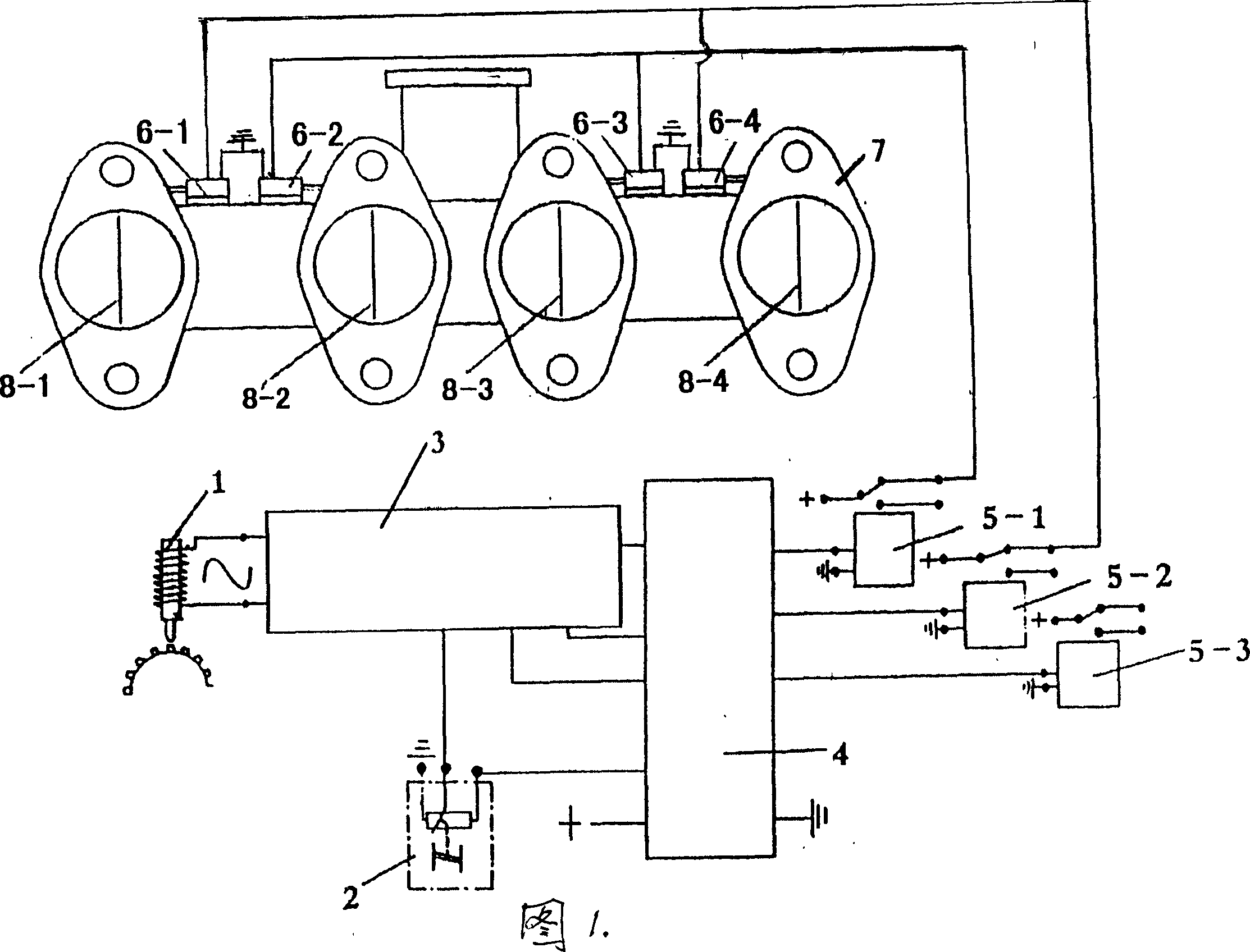
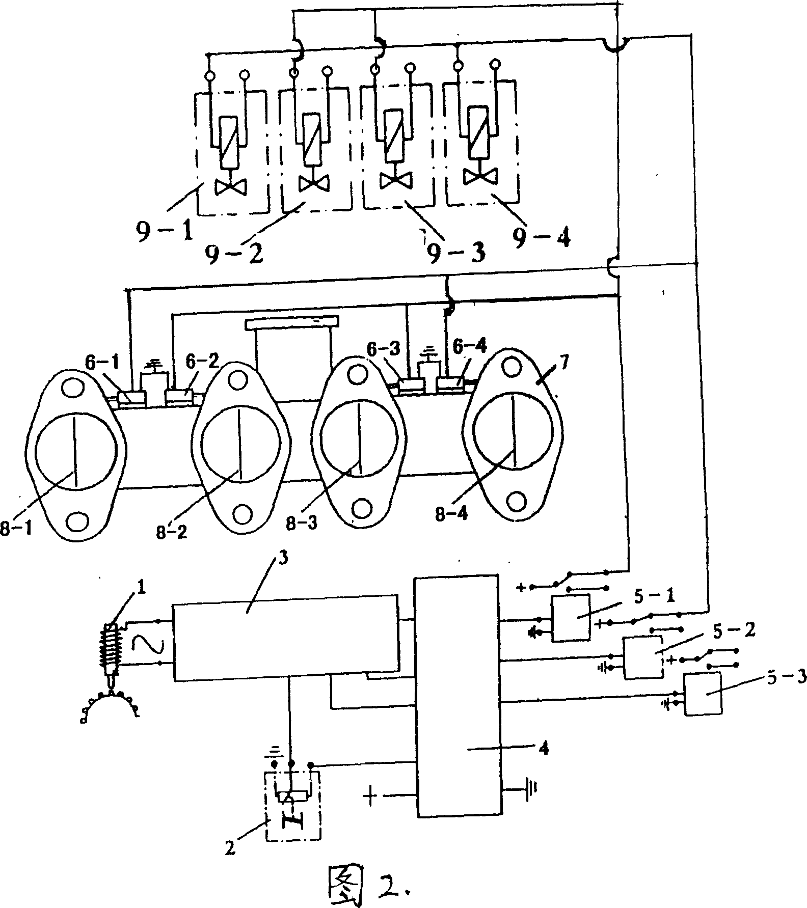
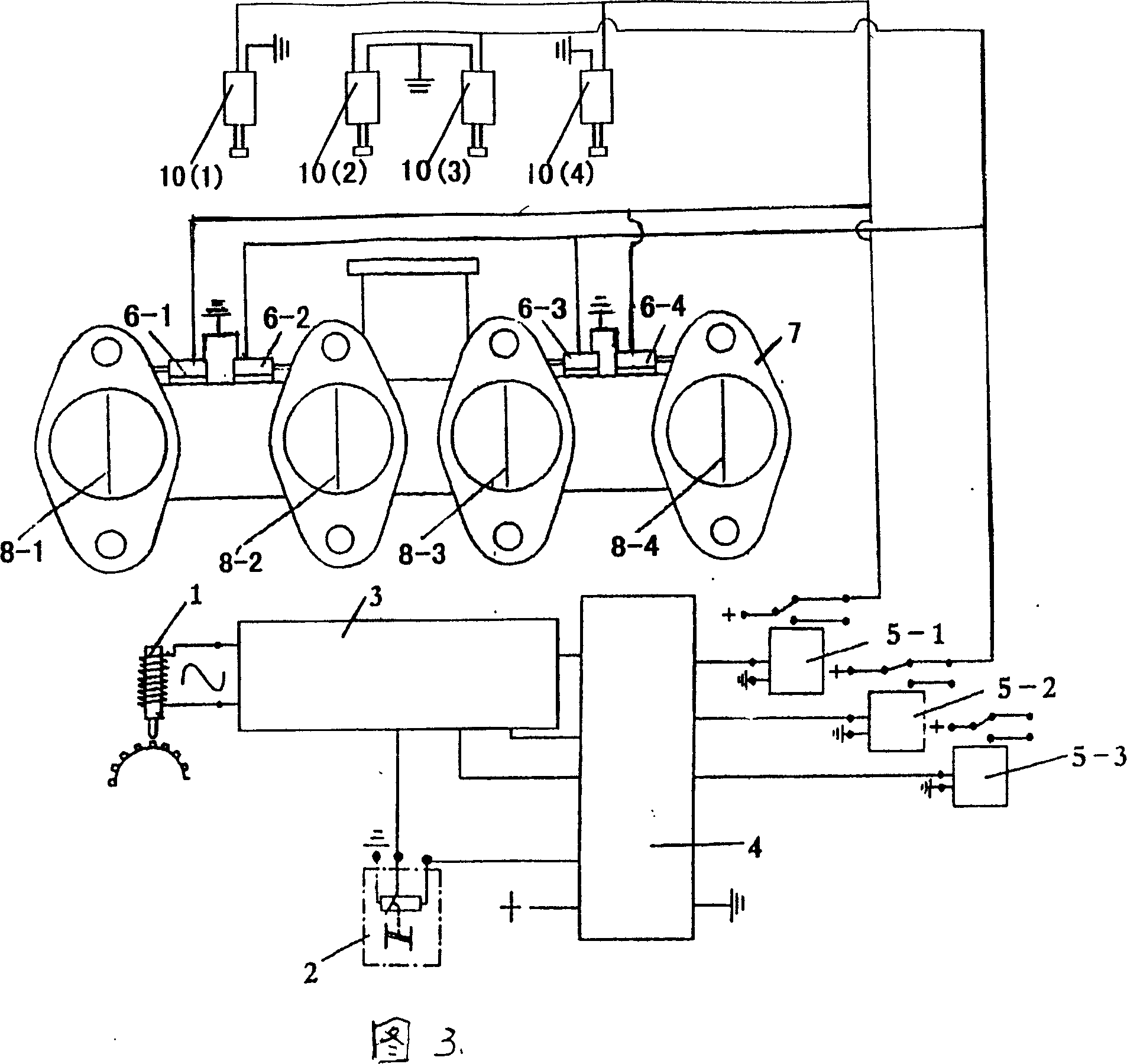
[0031] With reference to accompanying drawing 1, the present invention is by engine throttle position sensor 2, engine speed sensor 1, signal processing sampling circuit 3, microcomputer processor 4, switch command output channel 5-1,5-2,5-3; 6-1, 6-2, 6-3, 6-4 and the air baffle plate 8-1, 8-2, 8-3, 8-4 formed in the intake pipe 7, each branch pipe.

[0032] Accelerator position sensor 2, is installed on the starting point of throttle speed regulating stay wire, is driven synchronously sliding by accelerator pedal and stay wire, and engine speed sensor 1, is installed in the top dead center observation hole place of engine energy storage flywheel.

[0033] The working condition of the engine is detected by the throttle sensor 2 and the rotational speed sensor 1, and is processed by the sampling circuit 3, sent to the microcomputer processor 4 for calculation, and two switc...


PUM


Abstract

The present invention discloses an automobile speed-reducing, braking, relieving and fuel-saving device. It is an automatic identification and intelligent control device consisting of accelerator position sensor, engine rotating speed sensor, signal processing circuit, microcomputer processor, more than two lines of switching instruction output channels, air intake baffle placed in the air inlet manifold and terminal actuator. Besides, said invention also provides its working principle and concrete operation method.

Description

technical field [0001] The invention relates to an automobile deceleration brake light-load fuel-saving device. Background technique [0002] When the car is running, deceleration and braking conditions often occur, and the engine slides from high speed to low speed. At this time, the engine does not need oil supply at all, but in fact the oil supply system is still supplying oil. [0003] When the car is running, most of the time it works under medium and light loads. At this time, the engine is running at high speed, and the oil supply system is also supplying a large amount of oil simultaneously. Wherein a part of fuel oil works and just can maintain power balance, and another part of fuel oil is superfluous waste. [0004] These two kinds of unnecessary fuel supply not only cause waste of energy, but also increase the emission of exhaust pollution. Contents of the invention [0005] The purpose of the invention is to provide a method and product which can save fuel ...

Claims


Application Information

Patent Timeline
IPC IPC(8): F02D41/26F02D13/02F02D17/00
CPCY02T10/42Y02T10/40
Inventor 张昌盛
Owner 张昌盛
Learn More