Sialon ceramic blade and cutting tool equipped therewith

A saran and ceramic technology, applied in the direction of cutting blades, manufacturing tools, accessories of toolholders, etc., can solve the problems of reduced strength, reduced strength, and difficulty in balancing the performance of blade materials

Active Publication Date: 2007-12-12
NTK CUTTING TOOLS CO LTD
View PDF10 Cites 9 Cited by
  • Summary
  • Abstract
  • Description
  • Claims
  • Application Information

AI Technical Summary

Problems solved by technology

However, the addition of titanium nitride or aluminum oxide tends to cause a decrease in strength
More precisely, due to the difference between the thermal expansion coefficients of titanium nitride and silicon nitride at high temperatures, the addition of the former tends to reduce the strength
On the other hand, since its addition turns silicon nitride into saran ceramics, the addition of the latter tends to reduce the strength
So it is difficult to balance the properties of the blade material

Method used


Image

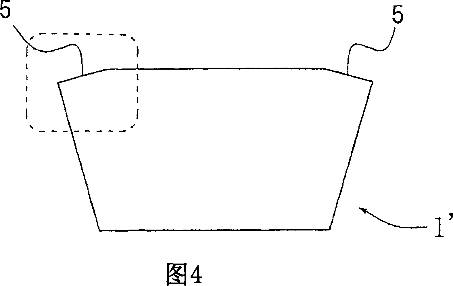
  • Sialon ceramic blade and cutting tool equipped therewith
  • Sialon ceramic blade and cutting tool equipped therewith
  • Sialon ceramic blade and cutting tool equipped therewith

Examples


preparation example Construction

[0077] A preferred method of preparing the saran ceramic blade according to the first invention will be described in detail below. A powder containing the constituent elements of saran ceramics, such as Si 3 N 4 Powder, Al 2 o 3 powder and AlN powder with sintering aid, specifically a powder of a rare earth element oxide, such as SC 2 o 3 Powder, Y2O 3 Powder, CeO 2 Powder, Dy 2 o 3 Powder, Er 2 o 3 Powder, Yb 2 o 3 Powder and Lu 2 o 3 The powders are mixed to prepare powdery raw materials. The powdery raw material includes particles having an average particle diameter of 10 μm or less, preferably 5 μm or less, more preferably 3 μm or less. The content of each component of the powdery raw material is determined by the composition of the blade after sintering. Typically, the powdered feedstock contains 95 to 50 mol% Si 3 N 4 Powder, 0.5 to 20 mol% Al 2 o 3 powder, 0 to 40 mol% AlN powder, and 0.5 to 5 mol% sintering aid. The prepared powdery raw material is...

Embodiment 1-23 and comparative example 1-7

[0138] (1) Preparation of blades

[0139] In the quantities shown in Table 2, by mixing α-Si with an average particle size of 0.5 μm 3 N 4 Powder; selected from Sc with an average particle size of 1.0 μm 2 o 3 Powder, Y with an average particle size of 1.1 μm 2 o 3 Powder, CeO with an average particle size of 1.7 μm 2 Powder, Dy with an average particle size of 0.9 μm 2 O3 powder, Er with an average particle size of 1.0 μm 2 o 3 Powder, Yb with an average particle size of 1.1 μm 2 o 3 powder, and Lu with an average particle size of 1.0 μm 2 o 3 A sintering aid composed of powder; and further A1 having an average particle size of 0.4 μm 2 o 3 powder, AlN powder with an average particle size of 1.3 μm, TiN powder with an average particle size of 1.5 μm, TiC powder with an average particle size of 1.0 μm, and TiCN with an average particle size of 1.0 μm to prepare powdery raw material powders. Then, each powdery raw material was pressed into the blade-shaped grinder...


PUM

PropertyMeasurementUnit
bending strengthaaaaaaaaaa
particle sizeaaaaaaaaaa

Abstract

This invention provides a long-life Sialon insert, the cutting edge of which is resistant to wear and hard to fracture, and a cutting tool equipped with the Sialon insert. Provided are a Sialon insert made of a Sialon sintered body including a Sialon phase comprising an alpha-phase Sialon and a beta-phase Sialon, and at least one element, originating from a sintering aid, selected from the group consisting of Sc, Y, Dy, Yb, and Lu in an amount of 0.5 to 5 mol% in terms of an oxide thereof, wherein an alpha value, which shows the proportion of the alpha-phase Sialon in the Sialon phase, is from 10% to 40%; the betal Sialon has a value of Z from 0.2 to 0.7 wherein Z is a variable of the formula Si 6-Z Al Z O Z N 8-Z and within a range: 0 / K or less at temperatures of room temperature to 1000 DEG C, and a thermal conductivity of 10 W / m*K or more at temperatures of room temperature to 1000 DEG C, and a cutting tool comprising a holder equipped with the Sialon insert.

Description

technical field [0001] The invention relates to a saran ceramic insert and a cutting tool equipped with at least one saran ceramic insert. More specifically, the present invention relates to such a saran ceramic blade whose cutting edge is wear-resistant and fracture-resistant, providing a blade with a long service life, and also relates to a cutting tool equipped with such a saran ceramic blade tool. Background technique [0002] The cutting tool usually has a support, which is called a tool holder, such as the tool holder 2 of the cutting tool shown in Figure 2 or the milling cutter shown in Figure 5, and the tool also has at least one fixed to one end of the support. Blade, which is a one-time cutting edge, is usually called "" throwable blade" or "cutting edge replaceable blade". The choice of material used for the blade depends on the type of workpiece, cutting method and cutting speed. These materials Concrete examples are cemented carbide, cermet, pottery, or CBN, o...

Claims


Application Information

Patent Timeline
Patent Type & Authority Applications(China)
IPC IPC(8): B23B27/14B23C5/16C04B35/584C04B35/599
CPCB23B27/141B23B2200/242B23B2200/283C04B35/597C04B35/6261C04B35/638C04B35/6455C04B2235/3217C04B2235/3224C04B2235/3225C04B2235/3229C04B2235/3843C04B2235/3856C04B2235/3865C04B2235/3878C04B2235/3886C04B2235/5436C04B2235/5445C04B2235/656C04B2235/658C04B2235/661C04B2235/766C04B2235/767C04B2235/80C04B2235/85C04B2235/9607
Inventor 虻川宏平丰田亮二小村笃史
Owner NTK CUTTING TOOLS CO LTD
Why Eureka
Try Eureka