
Method and device for reclaiming sulfur dioxide from countercurrent flue gas

A sulfur dioxide and recovery device technology, applied in chemical instruments and methods, separation methods, inorganic chemistry, etc., can solve the problems of flue gas turning into waste residue, consumption of natural resources, pollution, etc.

Inactive Publication Date: 2007-12-12
娄爱娟
View PDF0 Cites 57 Cited by
  • Summary
  • Abstract
  • Description
  • Claims
  • Application Information

AI Technical Summary

Problems solved by technology

The discarding method has obvious disadvantages: consumption of new natural resources; flue gas into waste residue, bringing new pollution; and emission of CO 2 , is a greenhouse gas, and the investment is large and the energy consumption is high
This will not only cause waste loss of ammonia, but also cause new pollution
This problem is an important reason why ammonia desulfurization technology has not developed well in the past for a long time

Method used


Image

  • Method and device for reclaiming sulfur dioxide from countercurrent flue gas
  • Method and device for reclaiming sulfur dioxide from countercurrent flue gas

Examples


Embodiment 1

[0068] A 440T / h fluidized bed boiler, burning coal with a sulfur content of 1.5%, and a flue gas flow rate of 500,000 Nm 3 / hr, SO 2 The content is 3200mg / Nm 3 , the content of other pollutants in the flue gas is: dust = 80mg / Nm 3 , SO 3 =55mg / Nm 3 , HCl=35mg / Nm 3 , HF=20mg / Nm 3 , NOx=100mg / Nm 3 , the flue gas temperature is 120°C.

[0069] The raw material for sulfur dioxide absorption is an ammonia water mixture with an ammonia weight concentration of 18%.

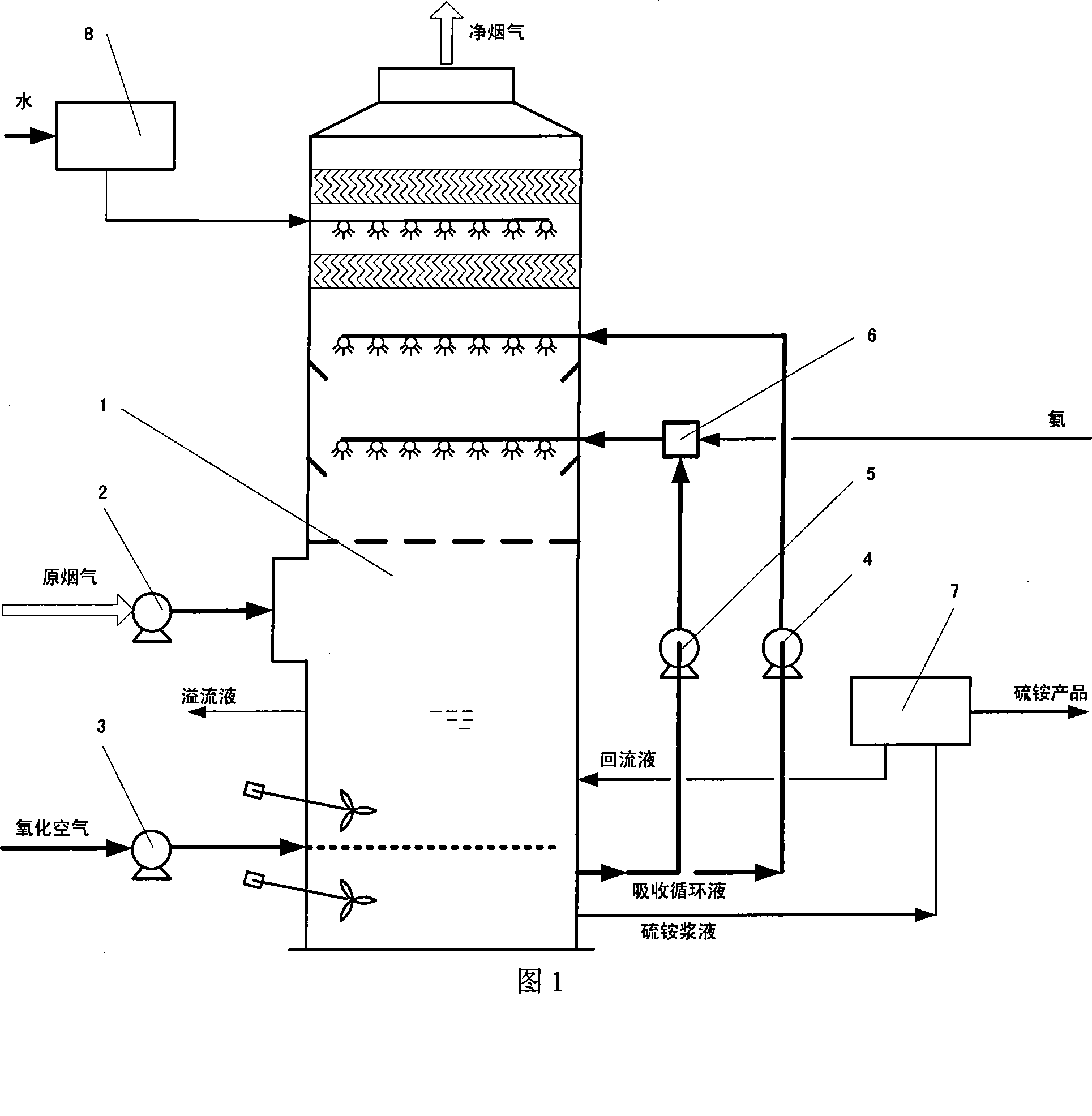
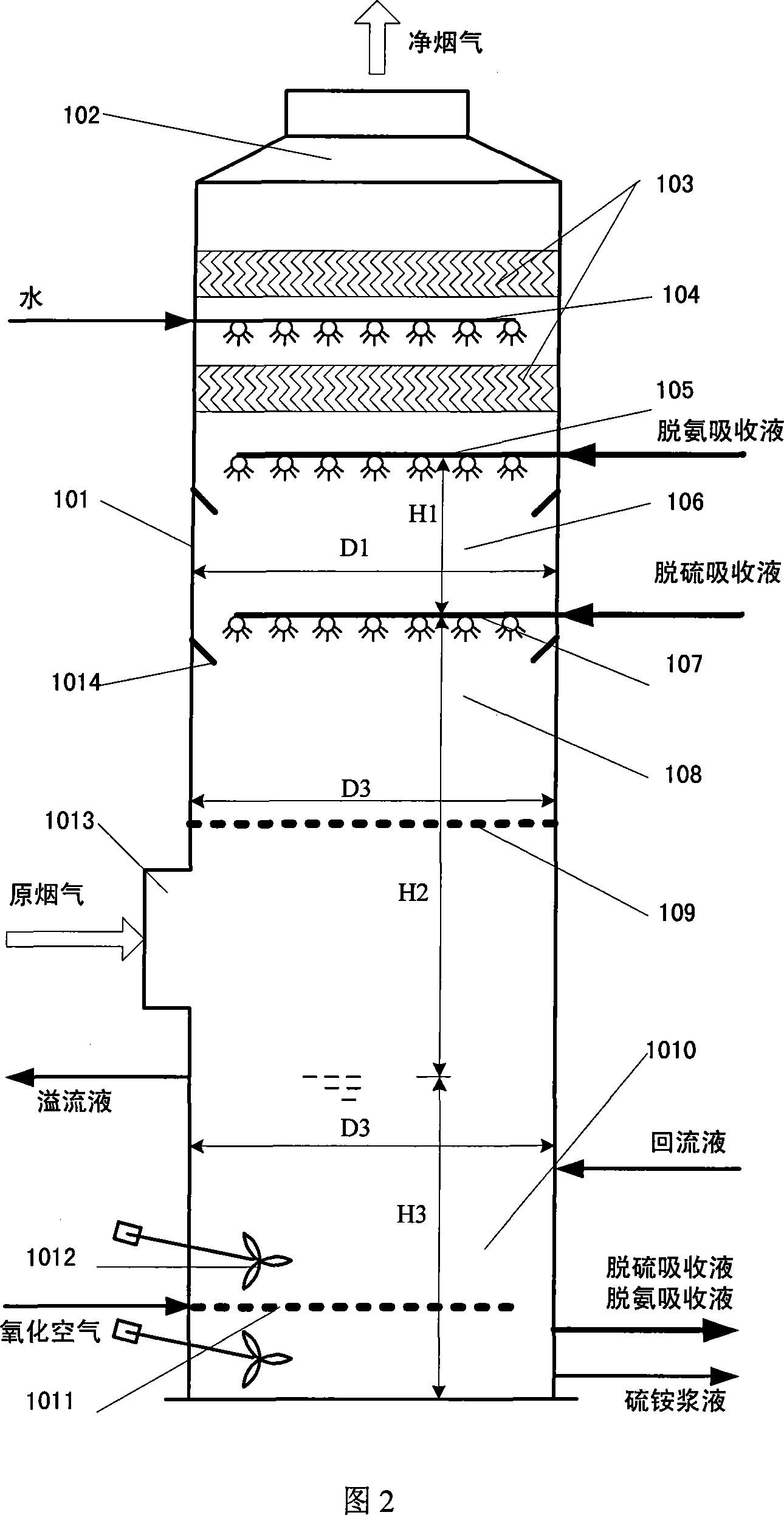
[0070] The center of the tower top of the sulfur dioxide absorption device is provided with a circular purified flue gas outlet, and a gas-liquid separation component is installed at the upper part of the tower body; a flushing water distributor connected to the water inlet is installed under the gas-liquid separation component; A deammonization circulating absorbing liquid distributor connected to the inlet of the ammonia circulating absorbing liquid is set under the deammonization absorbing liquid distributor; ...

Embodiment 2

[0082] A 300MW unit, burning coal with a sulfur content of 3.5%, with a flue gas flow rate of 1.2 million Nm 3 / hr, SO 2 The content is 9000mg / Nm 3 , the content of other pollutants in the flue gas is: dust = 220mg / Nm 3 , SO 3 =105mg / Nm 3 , HCl=35mg / Nm 3 , HF=20mg / Nm 3 , NOx=500mg / Nm 3 , the flue gas temperature is 135°C.

[0083] The raw material for sulfur dioxide absorption is liquefied ammonia.

[0084] The flue gas outlet of the sulfur dioxide absorbing device is set on the tower body close to the top of the tower, which is a rectangular mouth; the gas and liquid separation components are set on the upper part of the tower body; the flushing connected to the water inlet is set under the gas and liquid separation components Water distributor; a deammonization circulating absorption liquid distributor connected to the deammonization circulating absorption liquid inlet is arranged under the flushing water distributor; a deammonization zone is set under the deammoniza...


PUM

PropertyMeasurementUnit
Thicknessaaaaaaaaaa

Abstract

The invention relates to the new SO2 absorption device with three function areas, namely deamination zone, desulfuration zone and oxidization zone. It has purification air exhaust at the top of the SO2 absorption device, top of the inside of the tower composed of water and liquid separator of the flush water distributor, deamination circulation absorbing distributor connected to its inlet under the air and liquid separation component, under the deamination zone set with desulfuration circulation absorbing outlet connected liquid absorbing distributor, under which set the desulfuration zone, with absorbent liquid overflow outlet on the tower, and oxidization crystallization zone under the overflow outlet. It is low in investment, small in energy consumption, strong in gas treatment ability, high in efficiency, applicable for mass mode industrial application.

Description

technical field [0001] The invention belongs to the field of clean energy technology and clean coal technology, and is mainly used in thermal power stations, industrial coal-fired or oil-fired boilers, and SO 2 Flue gas recovery and purification. It can also belong to the field of chemical industry and environmental protection. Background technique [0002] Boilers or thermal power plants that use coal or oil as fuel emit a large amount of flue gas. These flue gases contain harmful substances such as SOx, NOx, HCl and HF, among which SOx is the main substance that forms acid rain. Depending on the type of coal burned, SO 2 The content is usually 300~5000ppmv (1000~15000mg / Nm 3 )between. However, the amount of flue gas is huge. In terms of coal-fired boilers, the steam scale ranges from 35T / h to 2500T / h, the capacity of the generating set ranges from 6MW to 1000MW, and the flue gas amount varies from 50,000 Nm 3 / h to 2.5 million Nm 3 , SO 2 Emissions from 1,000 tons / ...

Claims


Application Information

Patent Timeline
IPC IPC(8): B01D53/50C01B17/56
Inventor 娄爱娟
Owner 娄爱娟
Learn More