Electric hair drawing device

An electric and moving film technology, applied in clothing, hairdressing equipment, scorching hair roots, etc., can solve the problems of installation difficulty and high cost, increased energy consumption, noise level, vibration and discomfort of the hair puller, etc., to achieve no difficulty in manufacturing, The effect of improving hair removal efficiency and improving comfort

Inactive Publication Date: 2010-05-12
SUPERMAN GROUP
View PDF4 Cites 0 Cited by
  • Summary
  • Abstract
  • Description
  • Claims
  • Application Information

AI Technical Summary

Problems solved by technology

However, since the rotating parts of the hair-plucking assembly directly contact the skin, the use of a cam mechanism will increase energy consumption, noise level, vibration, and discomfort encountered by the user of the hair-pulling device during use, and the product structure is also more difficult and costly to manufacture and install.

Method used


Image

  • Electric hair drawing device
  • Electric hair drawing device
  • Electric hair drawing device

Examples


Embodiment Construction

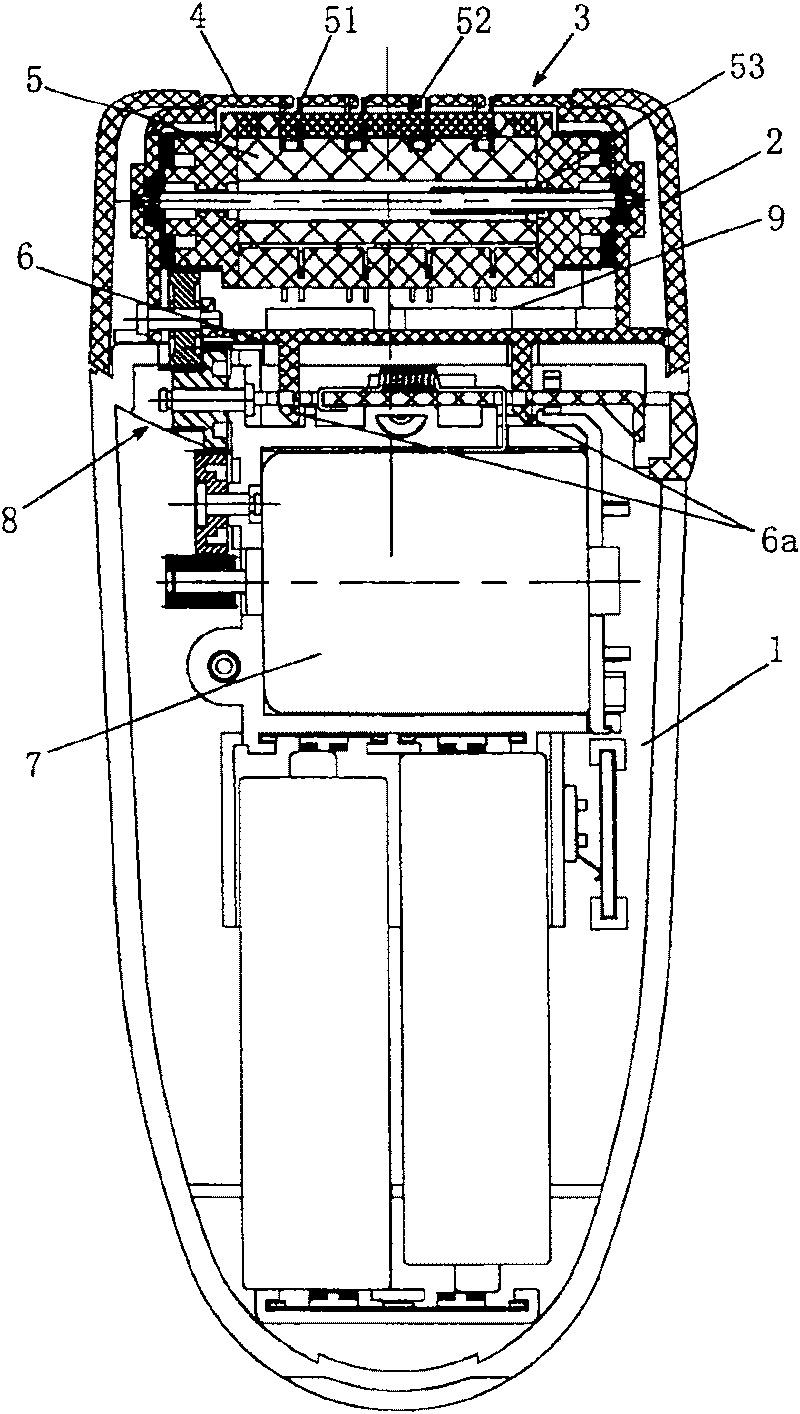
[0028] Such as figure 1 As shown, the electric hair puller includes a body 1 and a machine head 2 installed on the body 1 , and a driving motor 7 and a transmission gear transmission mechanism 8 are arranged in the body 1 .

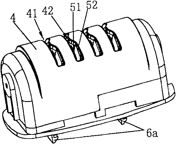
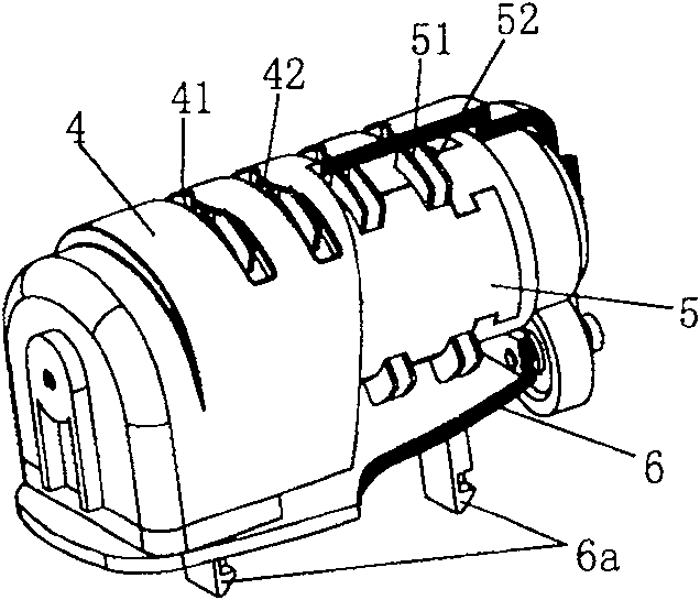
[0029] figure 1 The device on the head 2 of the electric hair puller shown has a Figure 2-5The hair-plucking assembly 3 described in detail in , the hair-plucking assembly 3 comprises a face mask 4 that contacts the skin during plucking, a hair-plucking head 5 and a base 6 that can be driven to rotate relative to the face cover, the face cover 4 and The base 6 encloses the accommodation chamber 9; the contour of the face mask 4 in contact with the skin is arc-shaped, and an arc-shaped groove 41 is formed on this position, and a smooth boss 42 is arranged on the edge of the arc-shaped groove 41; the hair-plucking head 5 Comprising a mandrel 57 and a rotary cylinder 58 that are assembled together and can only move in its axial direction, and a return s...


PUM


Abstract

An electrical defeatherer comprises a fuselage and a handpiece arranged on the fuselage. A driving device is arranged in the fuselage. At least one epilating unit is arranged on the handpiece. The epilating unit comprises a face mask contacting with skin when epilating, a defeather head driven to rotate with respect to the mask, and a base. The mask is provided with an arc-shaped groove and a convex rack at the top end of the groove. A stator and a moving plate capable of opening and closing with respect to the stator is fixed on the defeather head. When the defeather head rotates with respectto the face mask, the stator and the moving plate rotate in synchronism, and the moving plate can reciprocate along the shaft with respect to the stator, thereby realizing depilation in periodic cycle. Compared with the present defeatherer, the invention has the advantages of simple operation, good comfortability, and high efficiency.

Description

technical field [0001] The invention relates to a hand-held electric hair puller, in particular to a new structure of a hair collector formed by utilizing the relative movement of a veneer cover and a hair-plucking head, so as to improve hair-pulling efficiency and use comfort. Background technique [0002] The typical structure of prior art electric hair puller is as Figure 6 As shown, it is mainly composed of the epilator body A1, the motor A2, the reduction gear set A3 and the epilation assembly. Wherein, the main structural elements of the hair-plucking assembly include an arcuate shaft A4, a group of substrates A5 and thin clips A6, and each thin clip A6 is fixedly mounted on a corresponding substrate A5, that is, the substrate A5 supports the thin clips A6 drives the action of the thin clip A6, and the whole group of substrate A5 is connected together by a shift fork (not shown) (also can be connected by a bearing sleeve or a pivot pin) and rotates synchronously, and ...

Claims


Application Information

Patent Timeline
Patent Type & Authority Patents(China)
IPC IPC(8): A45D26/00
Inventor 应平祥
Owner SUPERMAN GROUP
Why Eureka
Try Eureka