
Manufacturing method for prestressed steel composite girder

A prestressed steel and composite beam technology, applied in the field of prestressed steel composite beams and manufacturing prestressed steel composite beams, can solve the problems of unavoidable compressive stress loss, difficult quality control, increased structural cost, etc., to improve structural performance and Effects of safety, reduced material usage, and reduced construction costs

Active Publication Date: 2012-09-05
RES INST OF IND SCI & TECH +1
View PDF2 Cites 2 Cited by
  • Summary
  • Abstract
  • Description
  • Claims
  • Application Information

AI Technical Summary

Problems solved by technology

[0007] The second traditional technique is to introduce compressive prestress into the concrete through the restoring force of the steel beam only
However, although this manufacturing method solves the problems of the conventional technology, its structure is very complicated
Therefore, the structural cost increases, and in particular, quality control becomes very difficult because it has a construction joint within the lower casing concrete
[0013] In addition, all the above-mentioned conventional methods of manufacturing steel composite beams have the structural problem that the stress caused by the self-weight of the steel composite beam (including the self-weight of the I-beam and the self-weight of the concrete) is used as the tensile stress of the lower flange concrete
[0014] In addition, in all the above-mentioned conventional steel composite beams, since the concrete is subjected to compressive stress of a predetermined strength while the steel composite beam is suspended on the bridge or abutment before the slab is formed, the compressive stress caused by creep deformation is lost over time. loss is inevitable

Method used


Image

  • Manufacturing method for prestressed steel composite girder
  • Manufacturing method for prestressed steel composite girder
  • Manufacturing method for prestressed steel composite girder

Examples


no. 4 approach

[0096] According to a fourth embodiment of the present invention, it is possible to manufacture a prestressed steel composite beam 400 having a beam web 315 via adjacent supports 320 and a lower flange 313 in the middle of the I-beam 310 to The sleeve 360 ​​extends in a parabolic shape.

[0097] In the fourth embodiment, since other manufacturing processes, structures, and effects are similar to those of the first embodiment described above, their descriptions will be omitted.

[0098] Figure 13 is a horizontal cross-sectional view schematically illustrating a prestressed steel composite beam manufactured using a method of manufacturing a prestressed steel composite beam according to a fifth embodiment of the present invention.

[0099] Now, referring to the attached Figure 13 A method of manufacturing a prestressed steel composite beam according to a fifth embodiment of the present invention is described. Similar to step S10 of the first embodiment described above, an I-...


PUM


Abstract

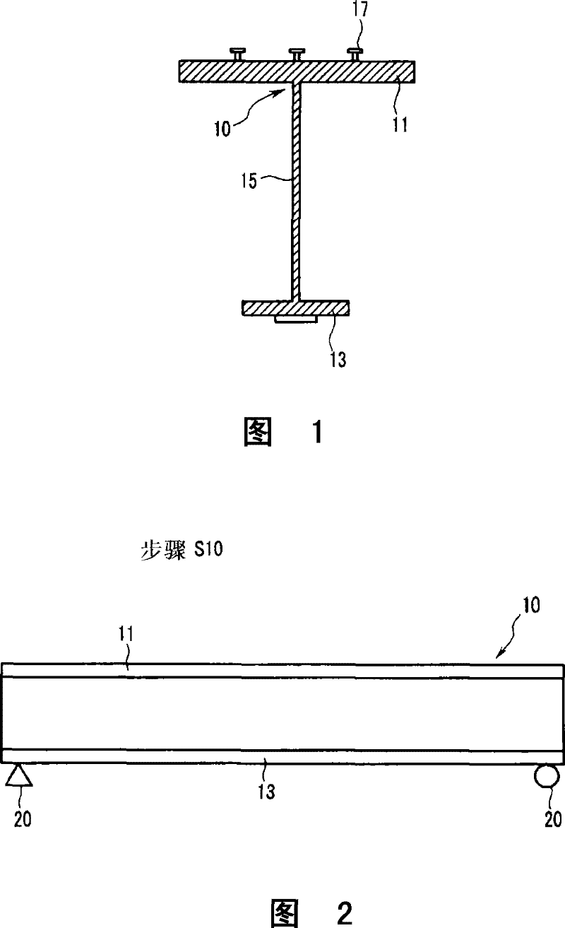
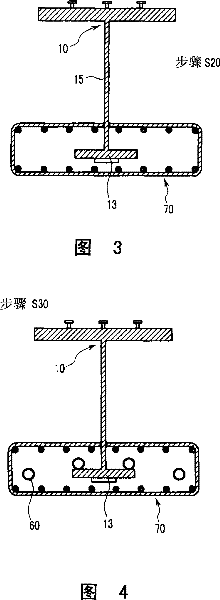
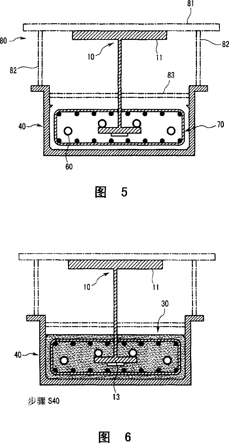
A prestressed steel composite girder and a method of manufacturing the prestressed steel composite girder are provided by using a steel beam and a concrete. The method includes steps of: placing the steel beam above the ground; installing a form, into which the concrete is to be inserted, to surround at least a portion of the steel beam, the form being suspended by the steel beam; inserting the concrete into an internal space of the form and curing it; and removing the form to compose the steel beam and the concrete. The prestressed steel composite girder includes a steel beam and a concrete composed to surround a portion of the steel beam so that stress caused by its self- weight can be applied on only the steel beam.

Description

technical field [0001] The present invention relates to a method for manufacturing a prestressed steel composite beam whose lower flange of a steel beam is reinforced with concrete and a steel composite beam manufactured using the method, and more particularly, relates to pre-introducing compressive prestress on the concrete to compensate for normal use. A method for manufacturing a prestressed steel composite beam based on the generated tensile stress, and a steel composite beam manufactured by the method. Background technique [0002] Generally, it is well known in the art that concrete resists compressive stresses but not tensile stresses. Prestressed steel composite beams have been designed to compensate for the tensile stresses that occur when dynamic and static loads are applied for compressive prestressing. [0003] Conventional engineering methods of pre-introducing compressive stress to concrete to provide a resistive section can be classified into the following th...

Claims


Application Information

Patent Timeline
Patent Type & Authority Patents(China)
IPC IPC(8): E01D2/00
CPCE01D2/02E01D21/00E01D2101/285
Inventor 李泌求
Owner RES INST OF IND SCI & TECH
Learn More