Housing

A shell and decent technology, applied in the direction of transformer/inductor casing, inductor, transformer/inductor coil/winding/connection, etc., can solve the problems of high cost and failure rate, and achieve the reduction of manufacturing cost and failure rate , The effect of reducing the production time

Inactive Publication Date: 2007-11-14
MOELLER GEBAUDEAUTOMATION KG
View PDF0 Cites 3 Cited by
  • Summary
  • Abstract
  • Description
  • Claims
  • Application Information

AI Technical Summary

Problems solved by technology

This results in higher costs and failure rates in manufacturing

Method used


Image

  • Housing
  • Housing
  • Housing

Examples


no. 1 approach

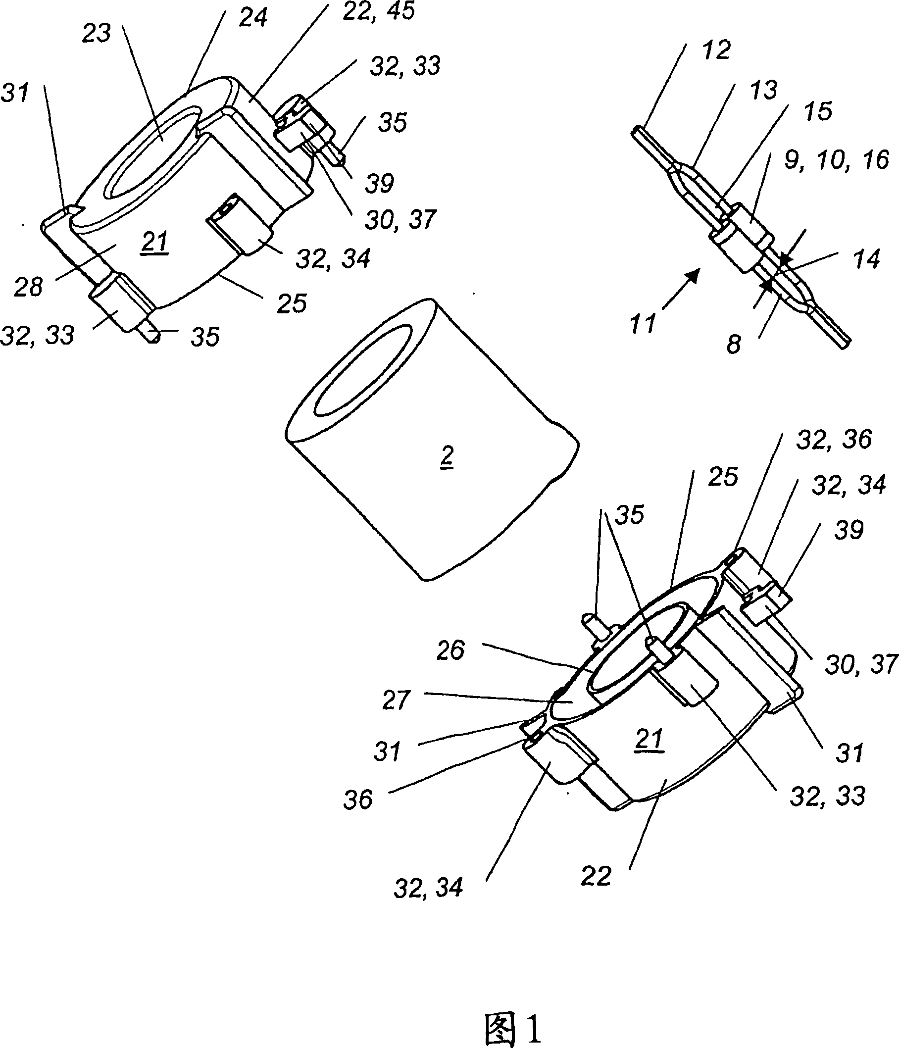
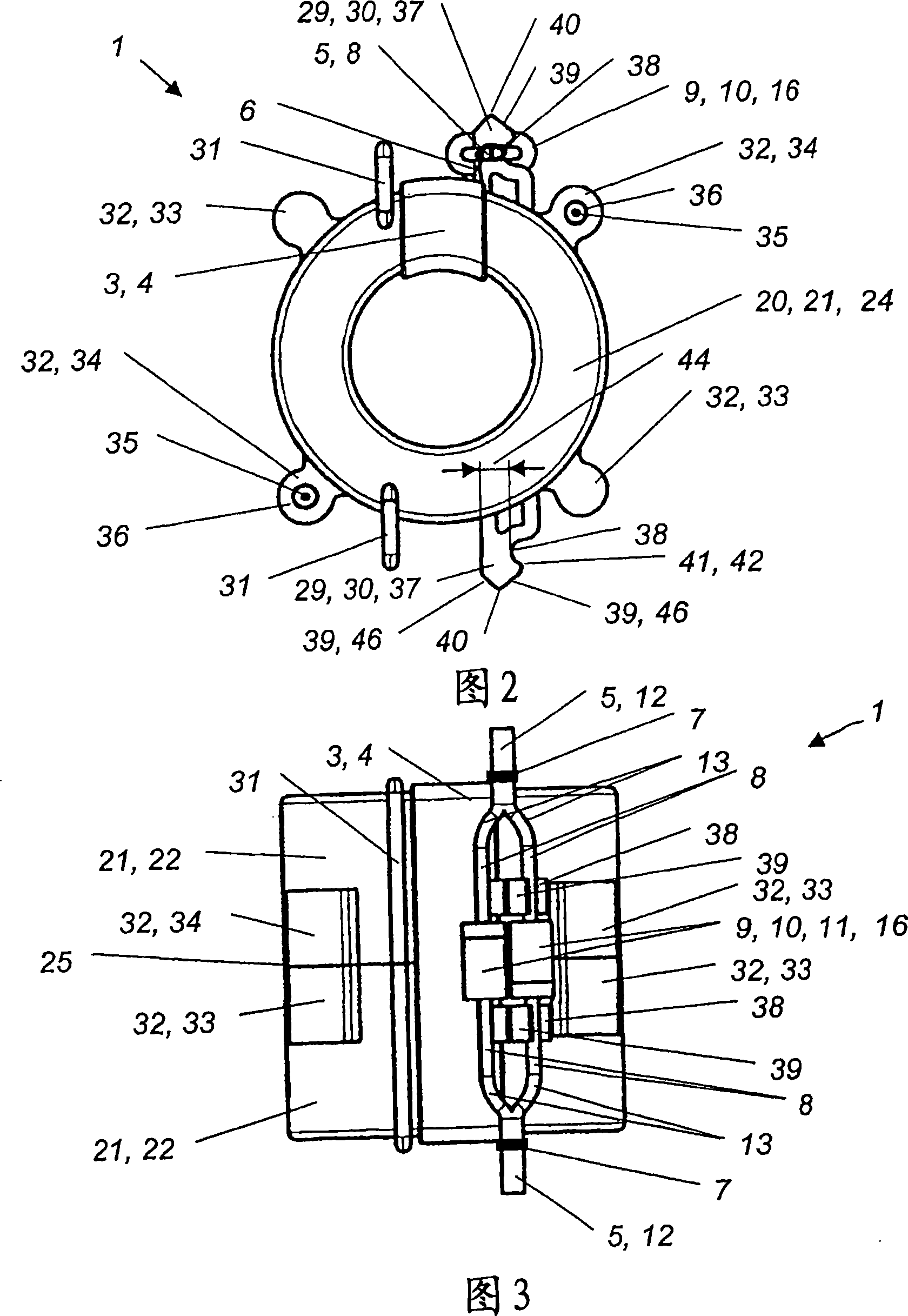
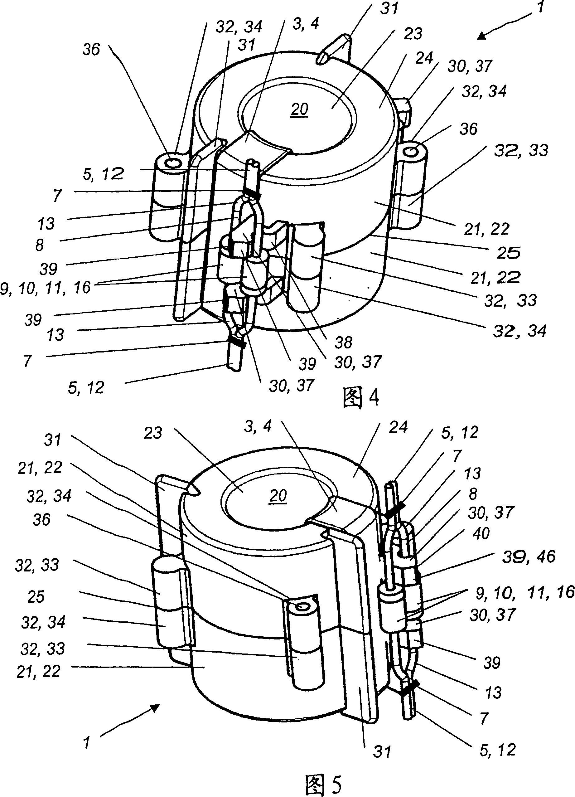
[0050] Clamping section 29 or partial clamping section 30 is arranged in a first preferred embodiment in such a way that at least one axially or radially wired electronic component 10 is substantially parallel to the housing surface, which is formed essentially as cylindrical housing surface 22 45 settings.

[0051] The clamping part 30 is preferably formed as a toothed extension 37 which has a receptacle 38 . The tooth-shaped extension 37 has a substantially rectangular cross section and protrudes from or is perpendicular to the outer cylindrical shell surface 22 , wherein the specific position depends on the outer dimensions of the electronic components 9 , 10 to be accommodated. In the preferred embodiment shown in FIGS. 1 to 5 , the partial clamping portion 30 is arranged such that the distance between it and the outer cylindrical shell edge 25 is at least greater than the shell of the electronic component 9 , 10 to be accommodated. half the body length.

[0052] Part of...


PUM


Abstract

The invention relates to a housing (20) for a magnet assembly (1), e.g. for housing a preferably annular magnetic core (2) of a differential current converter in a residual-current circuit breaker. According to the invention, the housing (20) consists of several parts and is configured from an insulation material. At least two conductive contacts (5) for connecting the ends (6) of at least one conductor loop (3), such as e.g. a secondary winding and/or a tertiary winding (4) of the differential current converter are configured on the housing. To improve the automated production of residual-current circuit breakers, the conductive contacts are configured as connecting conductors (8) of at least one electronic component.

Description

technical field [0001] The invention relates to a housing of a magnet arrangement, such as a preferably annular magnetic core for accommodating a differential current converter of a fault current protective switch, wherein the housing comprises a plurality of parts and is made of insulating material, and in the housing At least two conductive contacts are formed for connecting the ends of at least one conductor coil, for example the ends of a secondary winding and / or a tertiary winding of a differential current converter. Background technique [0002] The magnet arrangement is, for example, a component of differential current converters used in fault current protective switches. The magnet core or its housing is surrounded here by the primary winding, which is connected to the terminals and contacts of the drum controller when used in a fault current circuit breaker. The secondary winding and / or the tertiary winding, which are arranged on the magnetic core or its housing, a...

Claims


Application Information

Patent Timeline
Patent Type & Authority Applications(China)
IPC IPC(8): H01F27/40H01F38/30H01F27/30
CPCH01F27/306H01F27/02H01F27/324H01F27/40H01F30/16H01F38/30H01F41/10H01H83/144
Inventor A·泰蒂克
Owner MOELLER GEBAUDEAUTOMATION KG
Why Eureka
Try Eureka